Bridgie – A new look for a CNC router

When our Hackerspace, Pumping Station One, had it’s mini router repossessed by a member who was leaving, I decided to design a replacement. As always, I wanted to try out some new ideas on the build. I also wanted a project made primarily in metal to force me to get up to speed on using my CNC Bridgeport. The result is Bridgie.

Bridgie?
Bridgie was inspired by the Bridgeport’s sliding X axis, so the working name became Bridgie. The other inspiration came from a sliding chop saw. This was used on the Y axis. The Y axis is remarkably stiff and makes the Z far stiffer than many other routers I have used.. All rods except for the Z are 20mm hardened steel and the 12mm ball screws add strength. The X is even stronger and the bearings always stay directly under the spindle. The entire machine weighs about 45 lbs..


Clean Design
I wanted a very clean design, so I designed it so it is totally self contained. The power supply, controller, limit switches and motors are totally contained inside the body of the machine. The only external interfaces are power and USB on the back. There is also a fan on the back that blows directly on the motor drivers and flushes any hot air out of the interior.
Spinning Ball Nuts
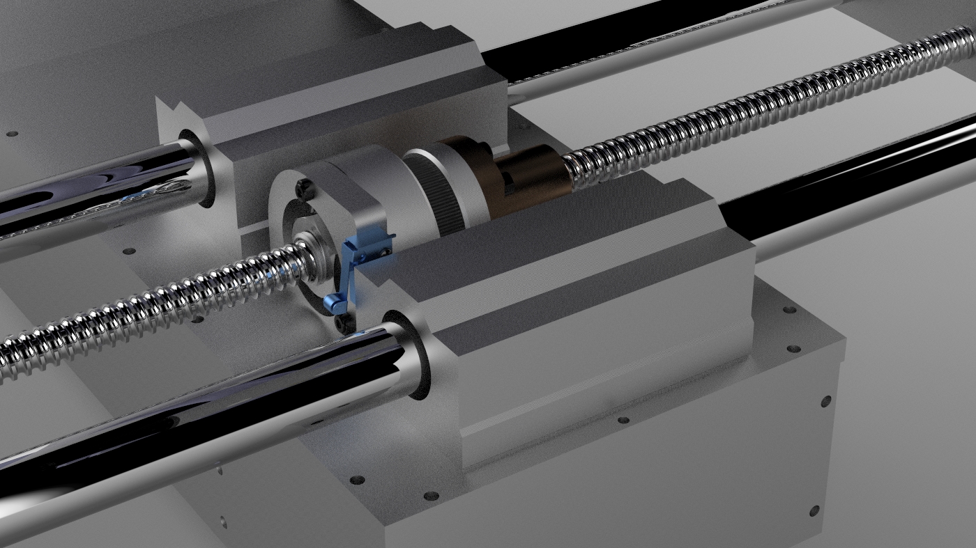
It uses 12mm ball screws on the X and Y axes. In order to bring the motors inside, I decided to use spinning nuts and stationary lead screws. This actually simplifies things because you don’t need to put expensive bearings on the lead screw, you just firmly attach it to the end plates. The lead screw becomes a structural member in the machine. The bearing on the nut is important for reducing backlash, so I used a large dual angular contact bearing. These were about $10 each from VXB. I did not take too many pictures during assembly, so here are some screenshots and renderings of the design.

Exploded view of the nut assembly.
Top view of X axis nut area

Bottom view of X axis
Controller and Firmware
The controller is an Azteeg X3 with a Viki LCD. I have used the X3 on a lot of projects. It worked really well on this project because it has the on board SD card and works well with the Viki LCD. The firmware is a highly hacked version of Marlin. Here is what I changed.
- Totally altered the LCD menu system to be right for a router.
- Tore out all the temperature stuff.
- Left in the extruder features in case I want to add a rotary axis. I have used the extruder as a 4th axis successfully on other projects.
- Added a Z zero touch plate feature.
- Added a G54 machine offset like feature in EEPROM. You you set a 0,0,0 for your workpiece, you can recall this later if there was a power failure or other crash.
- The arrow keys on the Viki jog the machine. In jog mode the up and down keys jog in XY. The rotary encoder is still active and sets the rate of the jog, so you can jog XY in fast, slow and micro mode all from one screen. Z can be jogged as well on it’s own screen.
- There is a feedrate override feature on the main screen to speed up or slow down the feedrate.
- All features are accessible via gcode, so pendant use is not required.
Homing and Work Offsets
The machine can be homed at any time. The Z homes first at the top of travel before homing the X and Y so this is less likely a chance to hit a clamp. Homing at the top of Z is not too useful for setting up your job, but the machine will now know the limits of travel and will never crash into the ends of travel.
The machine then homes at minimum X and Y. There are also two other configured locations called “park” and “access bit”. Park moves to center X, zero Y and top of Z. The head is out of the way in this spot so it is easy to clamp the work piece in this location. It is also has the minimum footprint in this mode for easy transport. It also has an access bit location that moves the spindle to the front for easy access to change the bit.
You can jog and set a work 0,0,0 anywhere you want. The machine resets it’s soft limits so jogging or G Code cannot crash at either end of any axis. If you restart the machine, you can recall the last work 0,0,0 so a previous job can be completed accurately.
Feature List
- Work area 12″ x 8″ x 3.5″
- T Slot table (larger on all sides than the work area for clamping).
- Sliding X table – Like a Bridgeport.
- Spinning lead screw nuts.
- Jogging with the pendant arrow keys
- Z touch plate. You can manual set the Z zero on the top of the workpiece or it can be done automatically with a touchplate.
- X,Y,Z limit switches.
- Park feature that moves the machine into it’s smallest size for transport.
- Weight: heavy…about 45lbs
- Soft limits. If you set a new work zero, the machine still knows the new limits of travel.
- Does not need a PC. It can run completely off the SD card with control via the pendant.
- No exposed wiring.
- Super quiet DC spindle.
- Cooling Fan directed on drivers, but flushes the whole interior.
- “Park” command shrinks the size to smallest footprint to help with transport.
- Freaking heavy at over 45lbs
Videos
To Do
- It would be nice to have easy access the the SD card. It is buried inside the unit now and you need to upload files to it via USB.
- Add a real feed hold (immediate deceleration like grbl does now)
Changes.
- There a few thing I would do to make it a little easier to fabricate. A few holes were difficult to drill and tap and some simple changes would make that a lot easier.
- I added an e-stop button since taking these pictures that cuts the DC power.


I really like this compact design. It is pretty quiet. Have you checked precision and accuracy yet? Is there much flex when Y is at its’ max?
Looks like you could easily add a fourth axis to rotate the spindle 180 degrees (like a pendulum).
Keep up the good work.