X-Controller-Controller (X-Controller minus controller)
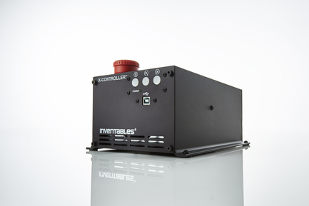
I am very happy with the X-Controller. It packs everything you need to run Grbl into a clean little package. It is super easy to hook up and move between machines. With that said, I had a quite a bit different idea in mind when I began the design.
The X-Controller was designed to be the motion controller for the X-Carve. The “X” in X-Carve was meant to signify that it was sold through a configurator and there were a lot of options. The X-controller was going to follow the same concept. It would support Grbl, Beaglebone Machinekit, Smoothy, and others. Additionally, alternate stepper driver PCBs might be developed.
To enable the configurability, the stepper driver section would be separated from the controller section. Every feature the stepper drivers supported would be available to the controller. The plug in controller PCB would control the features via firmware or jumpers and pots, depending on the power of the controller. The current X-controller has 4 stepper drivers, but (2) are wired together. In the split concept the controller card would decide how that was done.
At the time Easel was starting to get some real traction and Easel only supports the Grbl protocol. We decided that it was best to pick the easiest solution for our customers and make the X-Controller Grbl only.
My experiments in Beaglebone and PSoC have been such tangled messes of wires. I always wished I had that disconnected stepper PCB. I finally decided to make one.

The XCC Stepper Driver PCB uses the same Toshiba TB6600 drivers as the X-Controller. It fits in the X-controller just like a stock PCB, but it is quite a bit shorter. The interface side of the PCB has (1) 2×5 right angle header connector for each axis. Brought out the the connector are…
- Step
- Direction
- Torque (high=full current, low=1/3 current)
- Enable
- Micro-stepping selection
- VRef (sets the motor current)
- Ground and VMot
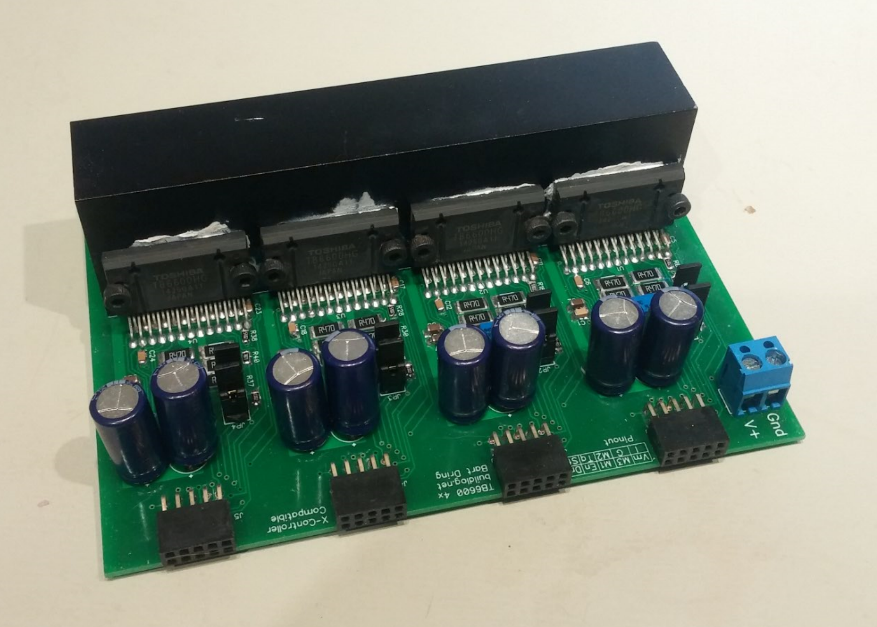
For this version, I put a current selection pot and micro step selection jumpers for each axis to simply testing. These function should be on the controller board, so most of these will be built without those installed. The PCB also needs 12VDC to 40VDC power for the motors. Each driver has a small 5VDC supply built in, so an external source is not needed.

Here is a snapshot of the schematic. This is just 1 of the 4 identical sections.

Here is snapshot of the layout. I was able to get everything on 2 layers.

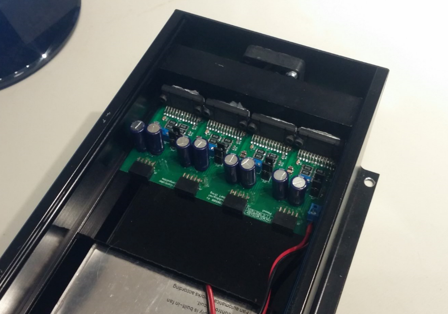
It fits into the X-Controller great. I used a small piece of black acrylic to fit the gap due to the shorter length. It is working perfectly. I have been testing it with my PSoC port manually wired in. A PSoC5 controller will probably be the first controller card I will have made.