NickelBot – Laser Controller

Here are some details on the custom laser controller I made for the NickelBot, wooden nickel engraving machine.
I want to use Grbl to control the machine. Grbl has support for lasers that allows better power control during the engrave. It also has the Core XY support I need for the H-bot mechanism it uses. The only feature I needed that it did not have is a hobby servo output.
A hobby servo requires a PWM signal. Normal Grbl runs on a ATMega328p cpu (Arduino UNO). The 328p has 3 timers that can be used to generate PWM signals. Grbl uses all 3 of them. You can attach more than PWM output to a timer, but the only timers that would work are only 8 bit timers. That is not going to give me the resolution I want.
A hobby servo uses a 1ms to 2ms pulse that repeats every 20ms. This means you are only using 1/20th of the duty cycle range. 1/20th of an 8bit signal is pretty rough. I could have used an Arduino Mega to get some more free timers, but I did not want to deal with the physical the size of a Mega.

My solution was to use a PSoC5. I have already ported Grbl to it and it has plenty of high resolution PWM components. I used the following PWM configuration…
- 16-Bit resolution
- 1 MHz Timer
- 20000 for the period (=20ms)
- 1000 to 2000 and my compare value range (1ms to 2ms)

This gives me a resolution of 1000 or 0.18° (exceeds servo’s capability)
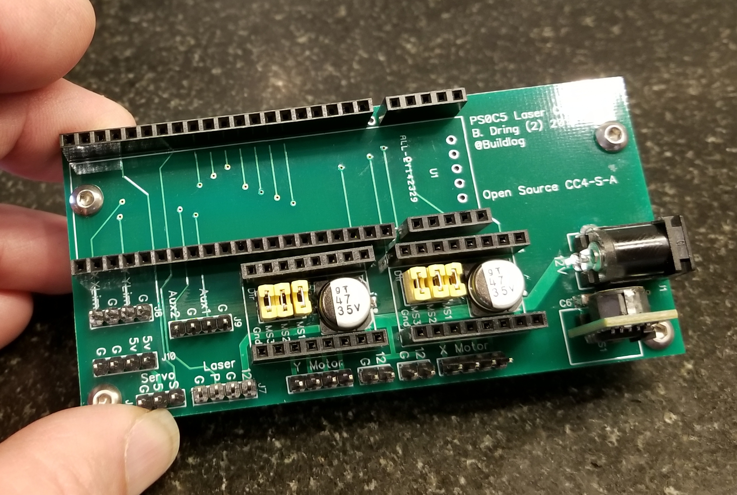
Here is an image of the raw PCB.

Here are the features of the PCB
- Has a socket for a CY8CKIT-059 PSoC5 development board (only $10-$15). The only drawback is the wiggly printed USB connector.
- 1A 5V power supply for servo
- (2) Sockets for Pololu footprint stepper drivers.
- (2) 12V fan connectors
- Servo connector
- Homing switch connector
- Laser connector (power and PWM)
- (2) general purpose I/O for buttons, etc
- Extra 5V power access connector.
Source Files.
Status
The board is fully tested and 100% functional. I have it hooked up the the machine and have tested the following.
- Home switches
- CoreXY motor control
- Servo control
- Laser PWM.
- Fans
Suggested Changes
- The control signal on the laser supply appears to turn on the laser if left open. Therefore if the controller is not powered or actively driving the pin low, the laser will fire. That is not good. I have not tested a solution, but I think a resistor of 2k-5k Ohm pulling the pin to ground will keep the beam off when not driven low. It should be quite easy to solder this resistor between the laser pulse pin and the adjacent ground pin.
If you want to be notified of future blog posts, please subscribe.


Can you post the board file ?
I have followed your work on the grbl and bought some of the psoc boards and am working on adding some features like using bluetooth with android for the interface so it can be stand alone using a cheap tablet for the interface.
Thanks so much for all you have done.
I will post all the sources after I have finished testing. I don’t want to post any mistakes.
I expect to be there within the week.
Just curious but why are the pins on the 5V connector ordered G G 5V 5V instead of having two 5V/G pairs?
No real reason for the G G 5 5 order other than it was quicker to route. I have not used them yet except as an easy access test point.
I am dying to try this project. I’ve been looking for something just like this.
Can you please release the pcb file?
I added the source files to this blog post.
I also have about 9 more blank boards that I would be happy to sell for $10 each (includes US shipping)
I would LOVE a few boards. I shot you an email.
Thank you so much for releasing the files and sharing the designs. This thing is beautiful.
It’s me again. The schematic PDF link leads to the gerber files on accident??
I cant find a PDF anywhere.
I think I fixed it
Thought of adding a jumper for connecting spi to the drivers like they have for the TMC, or maybe using bigfood socket?
would this work with this project? https://www.ebay.com/itm/ESP32-Development-Board-2-4G-Dual-Mode-WiFi-Bluetooth-Dual-Cores-CPU-/123231433219?_trksid=p2385738.m4383.l4275.c10
It looks like the ESP32 modules I use.
what parts are needed to populate the board besides headers? perhaps a BOM?