Grbl_ESP32 Development Board Instructions

Overview
These are the basic instructions for setting up and using the Grbl_ESP32 CNC board. This is an open source CNC controller. It is for sale on Tindie. The source files are located here.
Program the ESP32
It is always best to program a CPU for the first time not mounted to a board. You don’t know if the current firmware will cause harm in the new application. A simple blink program could damage an I/O pin if that pin is tied to ground or a voltage when mounted.
Setup the Arduino IDE
- Get the latest Arduino IDE from arduino.cc. (important…the latest)
- Install the Arduino Core for ESP32 by following instructions here.
- Using the board manager and other tools menus select the board you have (see below for what options to set.)
- Download the Grbl_ESP32 firmware from the GitHub repo. The master branch is generally more stable, but other branches will have the latest features.
- Connect the ESP32 board to your computer via USB
- Select the com port associated with the ESP32 module you have
- Compile and upload the code.

Configure Grbl_ESP32
Now that you know you have everything setup properly to program the ESP32, it is time to configure Grbl. There are only (2) files that typically need to be edited. The defaults should work in many cases, but it is good to know what options you have.
- cpu_map.h – This is the file that tells the firmware how the I/O pins should be used. The defaults will work with this board without changes.
- config.h – This has dozens of things you can change. The defaults will work, but other features may interest you. There are lots of comments in the file to help you understand them.
If you made any changes, compile and upload the code again.
Install the modules into the controller board
- ESP32
- Disconnect the USB and install the ESP32. Be sure the USB is aligned with the edge of the board and the pins are perfectly aligned with the holes.
- Motor Drivers (DRV8825 Recommended)
- Make sure they are installed correctly. (2) of the pins are labeled, match them up with the same labels on the drivers
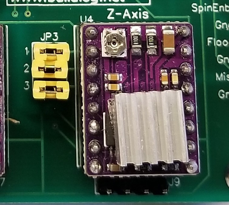
- Set your micro stepping level according to the driver specifications. (DRV8825) using the jumpers provided. The jumpers are labeled (1,2,3 to correspond with the labels on the drivers. See image below)
- Temporarily connect power (12VDC to 24VDC) to the board and set the current for the drivers. See the driver specifications on how to do that. They work well up to 1A without active cooling. They are set much higher by default and will generally have problems, so you should adjust them
- SD Card
- Install the SD module. Align the pin labels with the module and controller board. Note: The controller board has vcc labeled as 3.3V. It is actually 5V.
[image – Microstep jumpers]
Connect your motors, switches, etc.
If you need connectors, I recommend this set. It is low cost and will cover many projects. You can crimp the pins with needle nose pliers, but a crimping tool makes faster and better crimps.
- Motors
- The motor coils are connected to adjacent pins. A typical (but not always) motor wire color order would be red – blue – black – green.
- Limit/Home Switches
- Wire these as normally open and close to ground. Each switch has its own ground connection on the board to make things easier.
- Control Switches
- They wire the same as the limit switches, except the door should be a normally closed to ground. The door pins are connected with a jumper by default for people that don’t use the door feature.
- Spindle
- The Spindle PWM controls your spindle speed. If you want to run an on/off rather than variable speed spindle, just change the max RPM to 1. This means any RPM value with be full on. This is done via the $30=1 command. Note: Never connect these pins directly to a spindle or relay (non solid state). It is a very low current 3.3V TTL signal that must be connected to a speed control device or TTL relay driver.
- Spindle Enable & Direction – This is not supported at this time, The I/O pin is used for the SD on the default firmware.
- Flood Coolant – This is a 3.3V TTL signal to control a relay via the M8 command
- Mist Coolant – This is not supported in the default configuration. The I/O pin is used for the SD card on the default firmware.
Power up, test and tune.
- Get a gcode sender – Here is a good list of senders
- Many of the settings can be adjusted with $ settings. You can see what the codes mean here. Send $$ to see the current values. Send $xxx=xxx to change one.
- Motor Direction – Try jogging the motors. If they go the wrong way your can either spin the connectors 180° or adjust the $3 value in the $$ menu. You should always remove the power if you disconnect motors. The drivers can be damaged if connected while power is on.
- Tuning motor speed – By adjusting motor acceleration you can see how fast your motors can go with your setup. I like to see how fast the can go unloaded and then use about 75% of those values.
- Homing (optional, but highly recommended)- Enable homing with $22=1. Switches can be put at either end of travel. Try homing. If any axis does not move towards the switch, you can switch the homing direction with $23
Places to get help
- Comment section below
- Create an issue at GitHub
- Grbl_ESP32 Wiki (mostly ESP32 related only)
- Grbl Wiki (for general Grbl setup)
F.A.Q
- Coming soon.


Thank You very useful.
Is there any provision for a display? I was just thinking something simple like power, wifi/bluetooth status, maybe x/y positions, echoing gcode commands as they are received, etc…
Thanks!
Right now the primary displays are a PC or phone via Serial, BT, Web Socket or Web page
I have reserved some pins for I2C with the most likely use being some sort of an LCD display. It might be useful in a headless SC card type setup.
This feature will only be supported once we are done with all the others.
Which pins would be best for powering a small solenoid? I’m thinking specifically about controlling the cutter up/down motion for a vinyl/paper cutter.
No pins can directly drive a solenoid, they can only output a few milliamps. You would have to use a relay driver like this one.
You could simply use something like the flood coolant control to drive the relay. The gcode would need to have M8 for down and M9 for up.
Another trick I use for thing like this is to add another task to the firmware that looks at the current Z location about 20 times a second. If the current Z location is negative, activate the solenoid circuit. This requires a small mod to the firmware, but then you can use any CAM software to generate the gcode.
It is probably better in the future to ask questions like by creating new github issue.