First…. Most of the credit must go to Robin Baumgarten and Critters for the inspiration and firmware. While I have hacked and tweaked the firmware a lot, the basic design is still all Critter’s. He did a great job.
A lot of people have asked me to help them build one, so this blog post is here to help them out. It is easy and fun to design and build your own parts and electronics. You can also either use my or Critters 3D printed parts.
The Electronics
The electronics are quite simple and only consist of a few basic pieces.
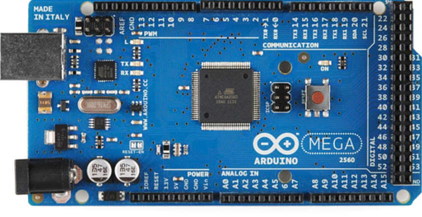
Arduino Mega – The firmware will not fit on an Arduino UNO, so you must use an Arduino Mega or anything using the the atmega2560 micro-controller. You can tpyically find a clone for less than $10.
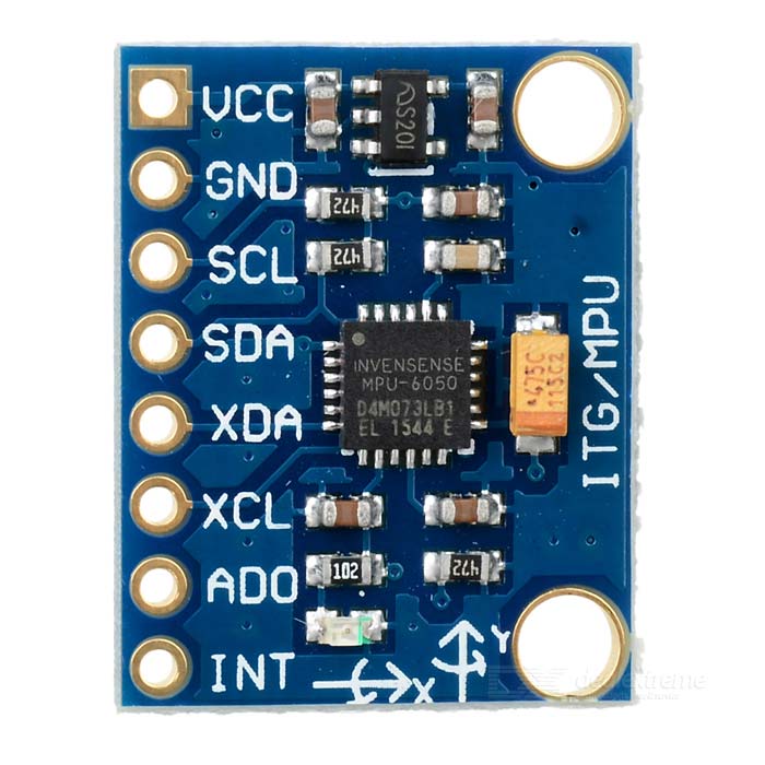
MPU-6050 – This is a 3 axis MEMS accelerometer and gyroscope. The easiest way is to buy a GY-521 breakout board. You only need to use the VCC, GND, SCL and SDA pins. Note: My shield also has the INT pin, but that was for experimentation. You can find these breakout boards on Amazon for less than $5.
Speaker – You need a small standard speaker. The sound quality is not great, so don’t invest in anything expensive. I used an 8 Ohm speaker, but anything should probably work. The speaker is hooked directly to the Mega I/O, so you also need a 100 Ohm resistor in the speaker circuit. Typically a 1/10w to 1/4w resistor would be used. Note: This resistor is included on my shield. If you use my 3D printed design you will want a 40mm diameter with very little depth to it. Note: Do not connect directly to an amplifier. It is not designed for that.
LED Strip – The FastLED library that is used, supports a lot of types. I like the APA102C (Dotstar) type. I have also tested WS2812 (Neopixel) types. Most of the testing I did was on a 1 meter 144 LED APA102C strand and it looked great. The game gets difficult when there are less LEDs, so I would recommend at least 90. I have also tested with (2) 1 meter 144/m strips soldered together and a giant 5 meter 90 LED/M strip. They all look and work great. The firmware supports up to 1000. Most longer strips are soldered smaller sections. It is easy to solder strips together like the image below. Be sure the 5V, Gnd, etc. are aligned the right way. I have some strips that are waterproof. That is not required, but does not hurt.
Note: Do not power the LED strip directly from the Arduino. Power it separately from a power supply. Note: My shield has an input for this. It will also power the Arduino.
Power Supply – Technically, you could need upwards of 40mA per LED. I bought a 10A supply and it has worked fine without getting hot up to 450 LEDs.
Life LEDs – The firmware supports remaining “life” LEDs. I prefer to use the main LED strip for this. It is fun to live within the limitations of the LED strip as the sole display. Using the strip also allows you to adjust the life count in firmware. The default is 3 lives per level, but I have boosted it to 5 for testing. Note: My shield uses different I/O pins for the LED than the original TWANG firmware, so you need to check this if using them.
Wiring
The image below shows all the required connections to the Arduino Mega. My prototype used male header pins poked into the Arduino headers. It worked fine, but wires did often pop out when removing the cover.
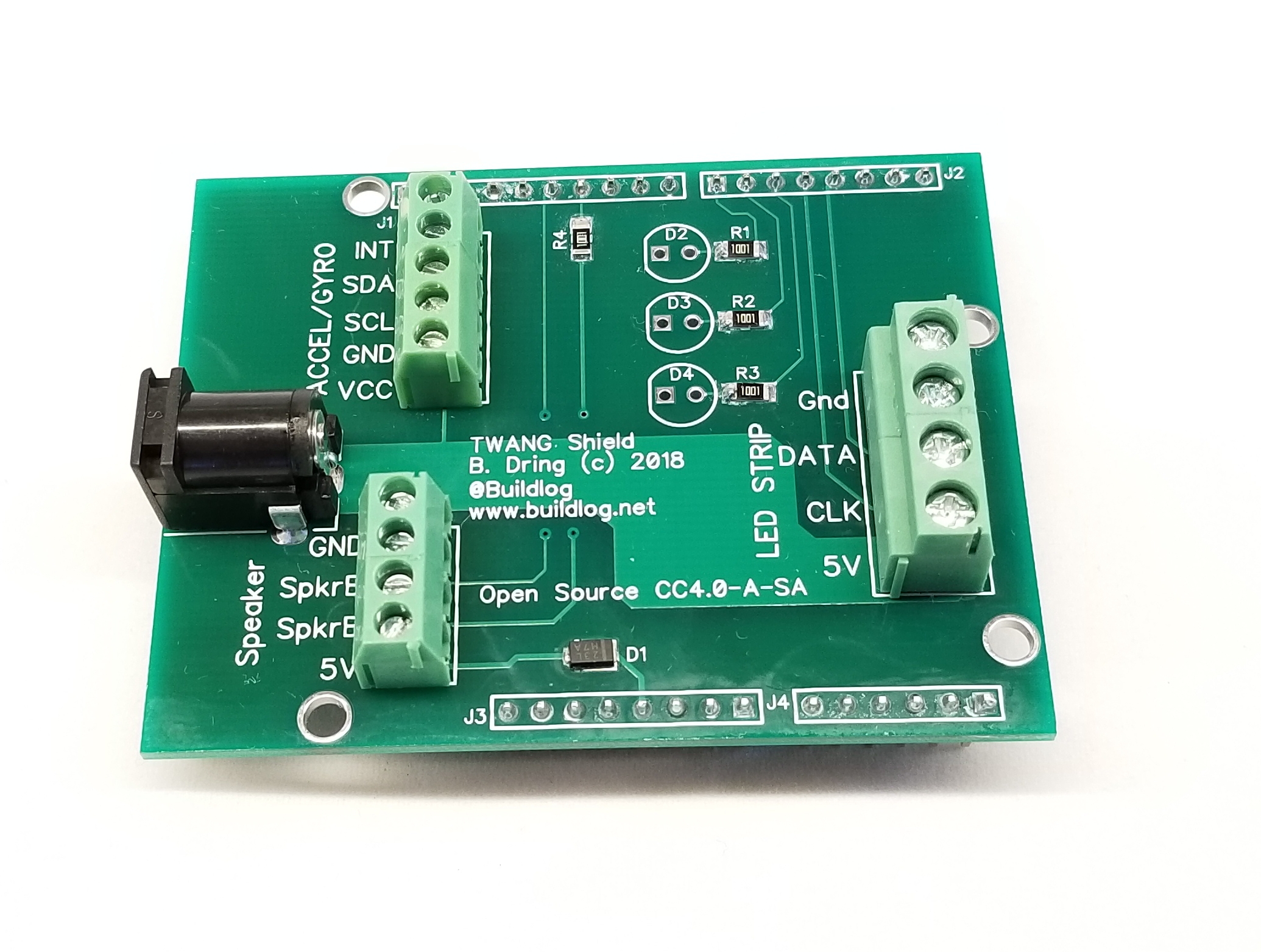
The TWANG Shield
While hand wiring is very simple, I found it to be messy and I worried about failures. I made a basic shield to clean everything up. Here are the features of the shield.
LED Strip Terminal Block – It is very easy to hook up the strip. It works with both 3 and 4 wire strips. The power comes from the shield and no additional connections are required on the strip. Connections are clearly labeled. 3 wires LED strips do not use the CLK connection.
Accelerometer Terminal Block: This has clearly labeled connections using the same names that are on the MPU-6050 accelerometer module. Just hook them up 1 to 1.
Speaker Terminal Block: This also has 5V and Gnd if your hacking requires these connections. The 10 Ohm speaker resistor is mounted on the board.
Main 5V power entry connector: This powers the LED strip. It also powers the Arduino. It uses a diode so you can also power the Arduino via USB for programming.
Arduino UNO compatible: While the default firmware will not fit on an UNO, future compact version might be possible.
Life LEDs – My enclosure does not use them, but you could wire some in. The resistors are included, but not the LEDs. You could solder LEDS on the board or remotely locate them and solder wires to the PCB.
All of this is fully compatible with the original TWANG firmware. I forked the original and added a few changes. I would be happy to merge back to the original some time in future. The firmware relies on several libraries. Follow the instructions on GitHub pages to get those libraries.
Hacking the firmware is quite easy. You should at least try editing some levels. More advanced hacking could improve the graphics and sounds. Please give feedback if anyone has made any improvements.
At a minimum you have to set the number of LEDs and the LED strip type in the firmware before compiling.
Video
(coming soon) This thing looks so awesome in person, but is nearly impossible to video due to the crazy brightness of the LEDs. A friend is going to help me try to get a decent video.
It’s difficult to beat. Only one person got all the way to the boss level and defeated it. Amazingly, it was Elan Lee. He loved the game and gave me some good ideas to work on.
Most people got killed in the second to last level. It has a lot of enemies and a conveyor that keeps pushing you back to the bottom. There is also a sneaky enemy spawner at the bottom that gets a lot of people. It is a great level, so I don’t want to remove it. I have added a few more levels before it to practice before that.
The Lava Pools. The lava pools confused some people. I changed the pools to look more red, flickering and scary when they are on and less scary when off. To me it looks more obvious now what to do.
The Sound. I love the chip tune style sound out of the Arduino, but it needs to be way louder. In a large crowd, you cannot hear it at all. I think it needs an amplifier or an option for an external speaker.
Boss Level: By design, the exit at the top of the boss level does not appear until all bosses are dead. People did not understand this and tried to exit out the top early, because the boss respawns below you after the first “kill”. That caused the players to try to leave the game without ending the level. If you exited the top in this mode, the player disappeared without a way back. This is very annoying if you get all the way to this last level. I fixed the code so you can’t goes past the second to last LED when the boss is still alive.
New Features: I asked several people for new ideas. I got some to work on, but already added one. The attack width is now adjustable. It will default to the old width, but you can change it per level.
More levels. A typical game lasts about about 1-2 minutes. I think a few more medium difficulty levels would help.
Scoring System: It would be cool to know how you did compared to others. It could display the score as a bar on the strip, with the max possible being the full length. You could then mark your level somehow by the strip. (Postit note flag, dry erase pen, etc)
Next Steps
Release all the source files.
Firmware: I have been hacking the code quite a bit. I’ll release my changes after some clean up and testing.
STL files: I have been using odd sized speakers harvested from some cheap external speakers. When looking looking to buy some, it seems like 40mm diameter is a good standard size that is cheap and available. As soon as I get some and test them, I will release the files for this size.
Sell on Tindie. My shield makes wiring super easy, but is definitely not required. I think I’ll sell everything, except for the Mega and LED strip. I’ll also just sell the assembled PCB by itself.
New Hardware:
Raspberry Pi Zero W: I have looked into several hardware options and this seems to be a good candidate. I think it will be a simple way to get good audio and connectivity. I have the accelerometer and LED strip working so far. The audio will be an I2S amp chip that will be put on a shield. The (2) drawbacks are boot time (20-30 second) and you are probably limited to APA102C (dotstar) type LED strips. Edit: I got a good portion of the code on the Pi running. It runs fine, but I don’t like the requirement for a slow and controlled shutdown of the Pi. It would require a button and some sort of visual feedback.
TWANG Pi Zero Prototype
If you want to be notified of future blog posts, please subscribe.
While the my TWANG clone has been running great, I wanted to clean up the wiring, so I made a shield to plug into the Arduino. I previously used header connectors plugging into the Arduino. The connectors go to three different places and come from all over the Arduino , so there were a lot of connectors including some single pin ones. I was worried they might pop out or fail. I also had to externally power the LED strip and supply power via USB to the Arduino.
The shield takes care of all of this and groups all of the external connections by function on easy to connect and clearly labeled terminal blocks. Here are the features I have…
Single 5V Power Connector: This connector powers the LED strip via a very heavy trace on the PCB. It also powers the Arduino. The Arduino is powered through a Schottke diode. If you plug in the USB, the Arduino switches to be powered by the USB. This allows you to program and hack the firmware while the LED strip is powered.
Terminal Block Connections: The wires are grouped by peripheral (Accel, Speaker, LED Strip) and clearly labeled.
LED Strip Connections: This powers and controls the LED strip. I have tested it with 4 wire (APA102, Dotstar) and 3 wire (Neopixel) strips.
Speaker Connection: There is an integral 100 Ohm resistor that is required when you directly power the a speaker from an Arduino. The terminal block also has 5V and Gnd in case you want to add a simple amplifier. BTW: Driving the speaker directly from the Arduino is plenty loud in my opinion.
Shield Size: The shield will work on both an Arduino Mega sized board or an Arduino UNO sized board. The TWANG firmware requires the extra memory of the Mega, but a tiny, reduced feature, UNO version could probably be made.
Life LEDs: There are provisions for 3 LEDs that are typically used to show remaining lives. I have not been using those. I prefer to use the LED strip to show remaining lives. I like working with the restriction of a 1D LED strip display.
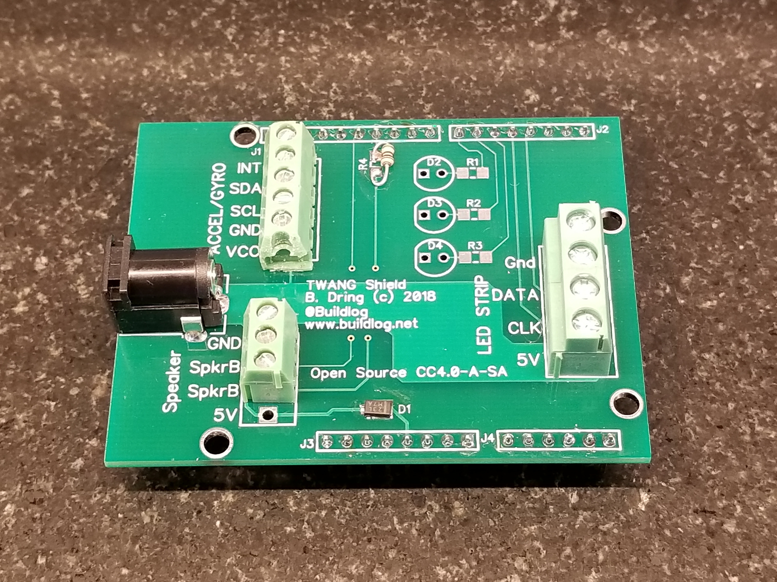
Prototype Assembly Notes: I did not have all of the correct parts for the build. I did not have a 100 Ohm SMD part, so I tacked on a through hole part. I did not have the right terminal blocks, so I cut one and only used 3 positions for the speaker. The correct parts will arrive soon.
Here are some more images.
Future Changes
I will probably get rid of the life LEDs.
I will add a large capacitor for sensitive LEDs, like Neopixels. Right now I just connect the cap to the terminal block.
I will probably sell the rest of this batch on my Tindie store in a week or two. I will probably sell assembled boards and full assemblies (less LED strip and Mega)
I will release of the documentation under an CC4.0-A-SA license.
If you want to be notified of future blog posts, please subscribe.
I have been a Patron of Robin Baumgarten for a while. He makes experimental hardware for games. His Line Wobbler one dimensional dungeon crawler is my favorite and I have always wanted to play it. It uses a door stop spring as the controller. An accelerometer in the knob allows it to work like a joystick and also detect the wobble used to attack the enemies.
Original Line Wobbler (Robin B.)
After seeing his playable Christmas tree version of the game, I had to make one for myself. I could not find any source files that he published, but I was able to find an open source clone called TWANG. The game is quite fun and surprisingly challenging.
Original Twang Version
Electronic Hardware
Here is a list of the electronics hardware used.
Arduino Mega. The Mega is way overkill for the I/O requirements, but an UNO does not have enough memory.
MPU-6050 3 Axis Accel/Gyro Breakout Board. These are available for about $5 and have good library support for Arduino.
Small Speaker. I bought a pair of external PC speakers at Micro Center for $4 and pulled out some 2″ speakers. You need to use a 100 Ohm resistor on one of the wires.
RGB LED Strip: The default code is written for the APA102 type strips. The FastLED library used also supports the cheaper WS2812 (Neopixel) strips. I used a 144 LED 1 meter APA102 strip. The Clock and Data type strips can work faster and they typically have an overall brightness factor that gives them a more useful brightness range than Neopixels. The brightness of these strips is insane and you typically run them at about 1/2 brightness.
Life LEDs: You can use 3 individual LEDs to indicate the number of lives you have left. I decided to skip that. I preferred the simplicity of a signal display element. I added a game over animation to the game to make it more clear that you are dead, dead.
Printed Parts
I created my own 3D printed parts. I was having trouble with the TWANG Thingiverse files. They are OBJ files and the parts are grouped. Cura was not creating good prints. My speaker was not going to fit anyway.
Chassis: I made a heavy walled enclosure to give it a little weight and make it extra strong.
Cover: The cover is also very thick. The speaker mounts in a pocket and is attached with hot glue.
Spring Clamp. This holds the spring to the cover securely. I also added a little hot glue to prevent it from rotating.
Knob Base. This is very similar to the official TWANG version. It has a longer, threaded interface to grab the spring. This parts takes a lot of abuse.
Knob Top: Snaps on, but also gets a little hot glue.
The Firmware
The firmware is well written and pretty easy to follow. You need to download a lot of libraries. Some can be installed from the Arduino IDE and some must be downloaded manually. This is pretty well explained on the Github page.
Everything works on a 60 frames/second loop. This includes the display and the sound. I was able to tweak a few things easily and add a game over animation.
The levels are very easy to edit. You really don’t need to know how to program. I tweaked a few to make them easier for beginners.
Assembly
Build Spring Assembly
Solder wires to the accel module.
Slide the spring clamp over the spring.
Assemble the knob to the spring top.
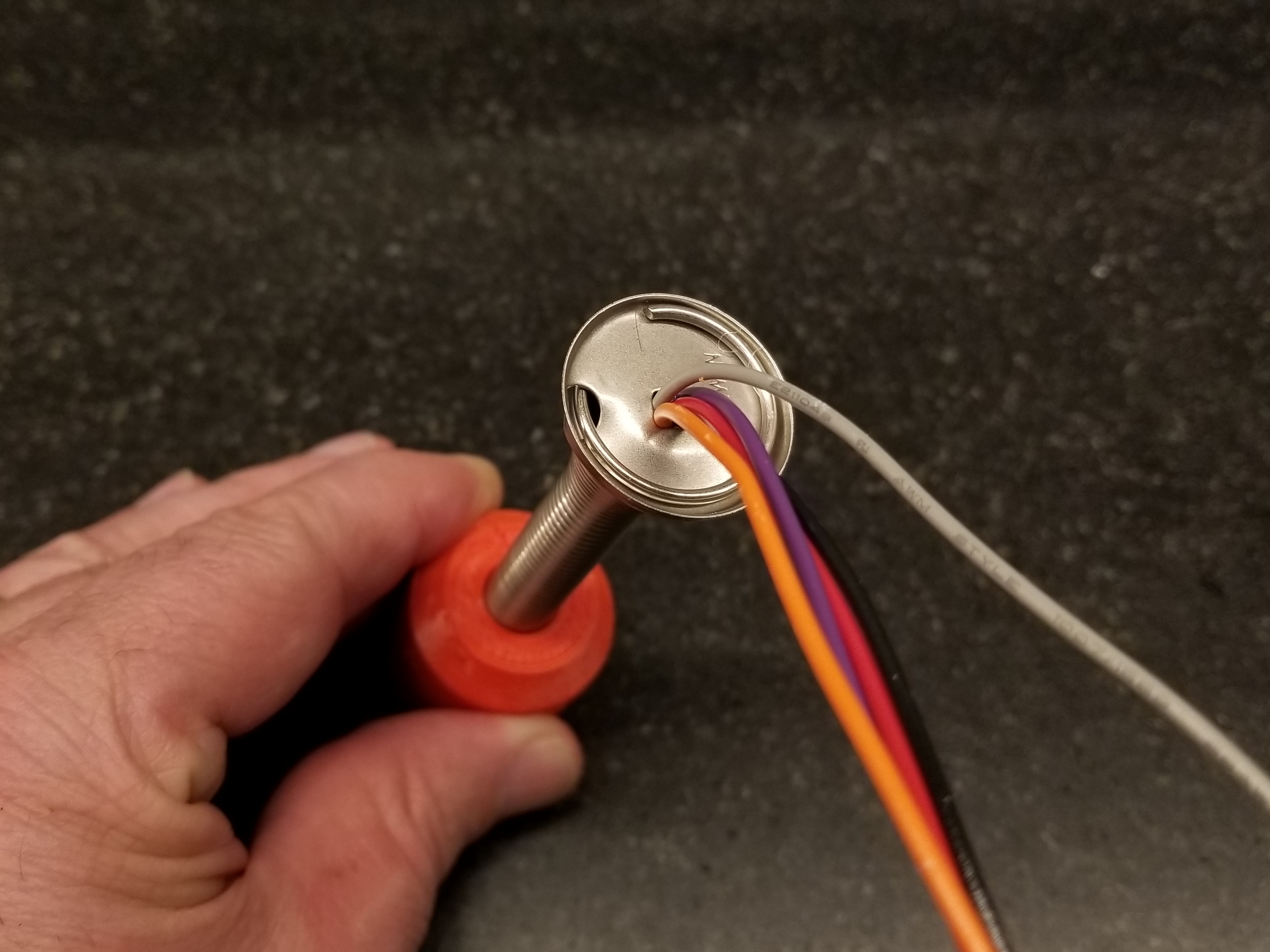
Feed the wires through the knob base and spring.
Screw the module to the knob base.
Attach the knob top to the knob base.
Attach Spring to Cover (make sure spring stays vertical when attaching)
Adjust the metal spring base until the spring stands vertically.
Put a little bead of hot glue in recess on the cover
Feed the wires through and place the spring in the recess.
Put a little hot glue around the spring where the clamp goes. Screw it down.
Attach Speaker to Cover
Blah
Attach some wires. Put a 100 Ohm, 1/4W inline on one of the wires.
Assemble Base
Install the Arduino Mega into the base with screws.
Connect all the wires per the graphic below. I wired the accel SCL/SDA at the left end, but you can also wire them to pins 20 & 21 at the right end.
Attach Cover
Usage
You need to power the LED strip with a separate 5V power supply. I used a 10A supply for my 144 LED strip.
You also need to power the Arduino. The easiest way is to do it via the USB port. You could wire the power supply in the first step to the 5V on the Arduino, but be careful to never power from the power supply and the USB at the same time or something will likely break.
Note: I have been hooking up the LED power first. When I only power the Arduino, I see some flickering of LEDs. That concerns me that it is drawing some power from the I/O pins.
Next Steps.
Make it Easier to Build: The wiring is a pain and probably not too durable. I used pins crimped into connectors that mated to the Arduino Mega. To make it easier I designed a little shield with screw clamps. It will also power the Arduino through a diode that will allow the USB to also be used. The speaker resistor is part of shield. It is also compatible with an Arduino UNO, so a pocket sized TWANG might be possible. That arrives next week. I will likely sell the extras on Tindie.
ESP32 Version: I would really like to try this. The sound and speed should be better and the ability to network with another player sounds cool. It is also smaller and cheaper.
Scoring System: Everyone want to compete.
Video
Here is a video of the Twang.
If you want to be notified of future blog posts, please subscribe.
The subject of skateboards came up about 2 weeks ago at meeting of local makers. One of the PS:One Hackerspace guys confessed he wanted to buy a longboard for getting around town. Longboards are more about basic transportation and carving smooth turns than doing tricks. The large size also encourages design and graphical creativity. I thought it was the perfect opportunity to get the creative juices flowing. It was a fun project that cost less than $50 to complete.
Once I get these ideas in my head I am totally obsessed with them. The only way to clear my brain is to actually build the thing whether I need it or not. I finally got some time between 2.x Lasers and ORD Bots orders on the CNC router last Sunday night.
Design:
3/4″ baltic birch deck.
Logo inlay on top near the front in a contrasting wood type.
The inly would be 1/4″ thick so minor dings and chips would not wreck the inlay.
Pockets cuts on the back to look cool, reduce the weight and give the board a little flex.
Miter the edges of the pockets for a cool look, make it more comfortable to carry and make it less prone to chipping.
Round the perimeter edges.
I really like the drop style truck mounting, but I would stick with a conventional bottom mount to start with.
Drop through mounting – Image from Moose
I found a whole bunch of longboard PDF templates here at Silverfish Longboarding. I started with the ST11 version. I felt the exposed wheels would allow more wheel, truck and mounting options without the wheels “biting” the board. The outline had a few sharp corners that I smoothed out. I didn’t want the line that is produced when you round the edge with the sharp corner. I imported an SVG of the snowflake logo from the PS:One wiki and sketched in some pockets on the back that looked cool, but still preserved the strength off the board with hope for a little flex.
I bought a truck and wheel kit off eBay for about $35 (free shipping). I only did basic research into what made a good choice. I just bought something that fit the basic requirements and looked cool (wide, reverse kingpost, big red wheels).
The basic deck is 3/4″ thick Baltic birch plywood.. The local high end lumber yard, Owl Hardwood, had some really nice 13 ply material. The top side is perfect. The back side is really good with only a few small blemishes and all the inner layers are high quality with no voids. Most plywood has knots and voids on the inner layers. The exposed edge and the pockets would show the inner layers so I wanted them to look good.
Fabrication Process.
Cut the inlay piece out of 1/4″ thick oak.
Mount the Baltic birch on the router and check for Z flatness in the inlay area. I mounted it on a sacrificial particle board. This board was clamped by itself, so unclamping the plywood would not affect the position of the sacrificial board.
Cut the pocket for the inlay slightly under sized. I then continued to profile the edges larger until it fit tightly.
Glued the inlay in place.
Cut the bolt holes for the trucks.
Cut the deck outline. I purposely cut extra deep into my sacrificial base so that I would have a clear outline of the board. This would allow me to flip it squarely to do the back side.
Cut the back pockets 1/4″ deep.
At the last minute I decided to add the the PS:One logo to the back as a 1/8″ deep pocket. It turned out to be my favorite detail.
Used a 1/2″ 90 Deg V bit to miter the edges of the pockets. I did a profile pass on the pocket lines set inside the line 0.02″ to make sure the tip was always inside the edge for a clean cut. The depth was set to leave 1/16″ of the original pocket wall.
Unclamp the deck.
I used a 3/8″ 1/4 round bit with guide bearing on the router table to round the edges.
Sanded.
Stained using Minwax Golden Oak stain. It is a light colored stain that varies quite a bit with the wood type.
Sealed. Minwax Satin Poly Urethane.
Time:
Design, research, ordering parts…about 1 hour.
Total time on the router…about 1 hour.
Sanding and Finishing…about 1.5 hours.
Cost:
$10 worth of baltic birch
$5 1/4″ x 8″ oak for inlay
$35 trucks and wheels.
Already had all bits, stain and varnish
TO DO:
I want to laser cut a bunch of little PS:One snowflakes out of grip tape and sprinkle them on the deck.
Hind Sight:
I am not super happy with the way the baltic birch stained. Woods like that can look blotchy due to varying wood density. I might have done better pre treating with a wood conditioner the birch or going without stain.
I saw this flat-pack inspired inspired playhouse over at inhabitots. Flat-pack is a form of a Ready-To-Assemble (RTA) product that ships in a flat state. The latest flat-pack craze is to see how efficiently you can pack the pieces into the raw sheet. The parts usually can be assembled without fasteners.
Gregg Flieshman has taken the look and assembly features to the extreme and produced some amazing designs. I was originally lured in by the playhouses, but some of his furniture is even more fantastic. The concept is perfectly suited to home router and laser folks because everything is done in the flat and there are no need to expensive, hard to get fasteners.
My son is a Boy Scout. My neighbor and friend is one of the Scoutmasters. He stopped by this week with a flyer for a brand new merit badge on inventing. He thought I might get a little excited about. He was right.
I work as a Mechanical Engineer, but when kids ask me what I do, just for fun, I often say that I am an Inventor. Their reaction is a mix of amazement, curiosity and skepticism. You don’t hear people refer to themselves as Inventors. Is this an archaic term? Is this something bestowed posthumously? I think I will try it on adults for a while to see their reaction.
The requirements for the badge are pretty ambitious. Here is the short version of what you need to do.
Interview or research someone who has invented something.
Learn about Intellectual Property and Patents.
Find scout related inventions.
Learn about patent infringement.
Suggests improvements to scouting equipment.
Come up with your own invention, build a model and working prototype of it.
The only major beef I have with the merit badge is that is does not make any reference to open source work or alternative licensing options.
I am sure he will get started on it as soon as he returns from summer camp.
You are currently browsing the Buildlog.Net Blog weblog archives for the Kid Stuff category.