Pololu and StepStick style stepper motor driver modules are great, but they have limited power. If you want more power, you will need to use larger stepper motor drivers like the one shown above. While the small modules are limited to about 2A. I have seen these stand alone drivers deliver close to 10A.
They often use opto-isolators on the inputs. Opto-isolators are used to block noise and spikes. Large machines with high currents can cause a lot of electrical noise. This noise can damage sensitive electronics and cause false triggers on switches or even false steps on drivers.
via Wikipedia
Opto-isolators use a non conductive gap. The signal crosses the gap using the light of an LED and an optical receiver. No noise, signals or spikes can cross the other way.
The LEDs have a forward voltage spec. You need to size a resistor to the voltage of your signal. The stepper drivers typically have a resistor built in for a 5V signal. They show that resistor in the simplified schematic on the case.
You can use a larger voltage by adding another resistor in series with their resistor. The operating manual will tell you how to size that resistor. Unfortunately, you cannot use a lower voltage.
Here is a simple circuit I have used to get around this. Just about any NPN transistor should work because the current required by the LEDs is typically less than 15mA.
I recently decided to update the Polar Coaster project. The primary reason was to update the controller to use Grbl_ESP32 firmware. I also thought I could make it smaller, lighter and remove a little cost.
Controller
The old controller was not custom made and just sort of tacked onto the back. This increased the size and didn’t look very good. It had a Bluetooth module, but you still had to stream the gcode. You could use an Android app, but that was still a little awkward.
Firmware
The controller runs Grbl_ESP32. This was recently updated to include pen machine features. This allows precise control and calibration of the pen servo. You can control the speed, timing and endpoints of the servo travel.
WebUI
The controller has a web server that serves a web app. This allows complete control of the machine. Web browser based control is ideal, because it is compatible with anything that can use a browser. We hope to add additional web apps for generating gcode from images and SVGs.
SD Card
This is a great feature. If you have files on the SD card, they can easily be plotted. The WebUI lets you upload files and then click play.
Stepper motors
Both versions use NEMA 14 motors. The original version used 34mm deep motors. I used these because I had some. They are overkill, because there is very little load on the motors. I bought some 20mm deep motors for the new version. These are even a little overkill. I am only running about 0.3A of current into each one. There are not too many options for standard stepper motors that are smaller and lower cost than these.
Gear Driven Rotational Axis
I decided to change from a belt driven rational axis to a gear driven one. Loop belts are a pain, because you have to order them from expensive places like SDP-SI and if you want to tweak anything, you might need to order a different size. I decided to use helix gears this time. These are 15° gears with a modulus of 1. They print and work great with my printer, even on a coarse layer height. The motor is mounted on slots and it is easy to get virtually no backlash. The helix keeps them quiet.
Rotational Platter
The platter rotates around a central bearing. This pulls (3) smaller bearings, that act like wheels, into contact with the PCB. This causes the platter to stay very flat, without wobble. I created a copper ring, plated with solder on the PCB to make it extra smooth and wear resistant. It also looks really cool and shiny on the PCB!
Buttons
Since there was a little room left on he board, I added three buttons. I have not added anything to the firmware yet. I think one will definitely be a homing button. I am not sure what to use the others for. I thought it might be handy to have a repeat button to repeat the last plot without having to fire up the phone app.
Battery Power
I made a battery case in the base of the machine to hold an RC style LiPo battery. I am using a 3 cell (11.1V) 2200 mah battery. The idle current on the machine with the WiFi running is about 80ma. When plotting it peaks at about 800ma. I think I should get about 2 hours of continuous plotting.
Future
Put kinematics into the firmware. currently files need to be pre-processed with the python script.
If you want to be notified of future blog posts, please subscribe.
I have done several pen and laser machines lately, so I decided to create a custom PCB for Grbl_ESP32 for these types of machines. This is a small (70mm x 60mm) PCB with all the features a pen plotter or laser cutter/engraver would need.
These typically use stepper motors for the X and Y axes. On pen plotters, the Z axis is controlled by a servo or solenoid. On lasers you need an accurate PWM for laser power control.
Here are the features of the PCB assembly
(2) Stepper Motor Driver Sockets for standard stepper driver modules.
(1) Hobby Servo Connector.
(1) High Current (10A max) Output Control. This can be used for a solenoid, fans, etc.
(2) limit/Home Switch Connectors.
Laser Power PWM connector
Removable Micro SD card. Upload files via Wifi to reliably run off-line.
5V 3A Step Down Power Supply
Standard DC Barrel Connector for power input. (9-28 VDC)
Power Output Connection for laser module.
Grbl_ESP32 Advanced Features
32-Bit dual core processor
Fast 120kHz step rates
WiFi
Access point or station modes
Complete web user interface
Telnet
Bluetooth Serial
Compatible with phone apps
Compatible with most serial port gcode senders
16 bit laser power control.
Core XY kinematics supported for T style machines.
RTOS (real time operating system) allows the use of custom tasks.
Precise servo control accurately mapped to Z motion, plus interactive calibration.
Precise control of solenoids via adjustable pull and hold strengths using PWM. This allows a strong pull, yet a cool hold temperature.
Instant On/Off – Unlike a Raspberry Pi, there is no long boot time or formal shutdown required. It is typically ready to go in a few seconds.
How to control it
There are several ways to connect to the controller, but to run jobs, you basically either stream the gcode or run it from a file on the SD card. The SD card is a great feature because it is free from connectivity interruptions and you don’t need to stay connected to your machine while it is running the job. You can quickly upload files via WiFi or remove it and plug it into your computer.
Serial port
This controller is compatible with virtually all of the serial port gcode senders for Grbl. The default baud rate is 115200.
Bluetooth Serial
This is a great way to use your phone to control a machine. When you connect via bluetooth, your phone or computer will create a virtual serial port. This means you can then use existing serial port based gcode senders.
Wifi – WebUI
The controller has a web server. The controller can create its own WiFi access point or connect to an existing WiFi network. You connect to the controller with a web browser and it serves a full featured machine controller to browser.
Controlling the Pen Up/Down Servo
The servo is controlled using a separate RTOS task on the controller. Grbl thinks it is running a normal stepper motor on the Z axis. Each time the servo task runs, it looks at the current position of the Z. It then computes and sets a position for the servo. You map the servo’s range to a Z range. For example the range could be set for 0-5mm. Any values of Z above or below this range would would be limited by the range, so any Z value above 5mm in this example would not move the servo past where it was at 5mm.
You can calibrate the end points of the servo to fine tune it. We use the Z axis resolution and max travel settings to do this. $102=100 (100%) would be no change to the first end point. %102=90 or $120=110 would be 10% changes in either direction. $132 works the same way for the other end point. Make sure you do not adjust the servo so it hits the physical end point of its travel. You will feel the servo continuously vibrating as it pushes against the end point. This is very hard on a servo and will overheat and damage it.
The servo updates its position 20 times per second. Therefore it will do a good job of respecting the acceleration and speed settings in the gcode.
The feature also uses the $1 (Step idle delay) setting. It the steppers motors disable, so will the servo and can be moved manually.
Additional parts you need
The controller uses plug in modules for the the ESP32 controller and the stepper motor drivers.
ESP32 Controller
The ESP32 controller needs to be a ESP32 Dev Module. It should have 2 rows of 19 pins. The rows should be spaced 0.9 inch (22.86mm) apart. Be careful: Some similar controllers have a wider pitch.
Stepper Motor Drivers
The drivers are the standard StepStick (Pololu) style footprint. The (3) microstepping selection pins (MS1, MS2, MS3) are all connected to logic high. This typically results in the highest resolution (1/16 or 1/32). The Grbl_ESP32 step rates are high enough to make that not an issue. I typically use TI DRV 8825 or Allego A4988 modules, but others can be used as long as the pins are compatible. The PCB silkscreen has the corner pins labeled. Use them to insure you correctly install your driver modules.
Source Files (coming soon)
A completely assembled PCB is available on Tindie. The profits from Tindie help me to continue to develop the hardware and firmware for projects like this. If you want to roll your own, the source files are linked below.
This is a quick blog post to document version 3.1. This is for sale at Tindie, but you can make your own via these files.
What is new
Integrated SD card socket: This no longer uses a plug in module.
Integrated 5V 3A DC power supply.: The previous plug in module used the same parts, but was adjustable. The adjustment was very sensitive and prone to drifting a little.
Last weekend at the 2018 Hackaday Superconference I gave a workshop called “Small Scale CNC/Robotics Workshop (Build a CNC Badge)”. It was a ton of work and a bit stressful, but I think it worked out about as good as I could have hoped. It was a lot of fun. Here is a quick post on how it went and what I learned.
The Idea
I have gone to a few conferences over the years including one previous trip to SuperCon. I have always wanted to challenge myself and do a talk or workshop. I wanted to inspire some people to consider getting started in DIY CNC. I proposed a 40 minute talk about how easy it is to get started if you work at a small scale. After that you get to build your first machine that is a DrawBot Badge. Badges are currently at “Peak Fidget Spinner” status, so that seemed like a fun idea. The bonus is that the badge is actually a fully functional CNC controller that can control a vast array of machines.
Workshop Approval Process
Superconference is announced early in the summer. Shortly after that, they put out the call for people to propose talks and workshops. I proposed my workshop with a suggested count of 20 people. I thought 20 would be a reasonable amount for my first time.
My workshop was approved the last week in September. Shortly after that, they announce that people can sign up for them. My conference sold out right away. They asked if I could add a few. I said I could probably add 5 more. They want a 10 attendee to 1 staff ratio. I asked my friend Jason Huggins (@hugs) to help and a Superconference volunteer also helped.
I now have only 5 weeks to order, assemble PCBs, kit everything, ship it and prepare the talk. This would prove to be a true #badgelife extreme experience.
State of the project before approval
I had a functional version of the badge with functional firmware. This controller could only run the badge and I wanted a full featured CNC controller. Having functional firmware was definitely a head start.
I didn’t want to invest significant time or order parts in case the workshop was not approved. I knew the timeline would only give me one chance at getting the PCB right. The PCB would include several features that I have never tried before. I decided to do another project that would include most of those new features. That was a good move, because I did make a few mistakes. One required a jumper wire soldered to a QFN pin, the other was easier, but ugly and vulnerable to breakage. Also, to upload firmware you had to manually trigger the bootloader because DSR is not the same as DTR (oops).
I made sure the new badge schematic was free of those issues, completed the layout of the PCB and waited for the workshop approval.
Production
As soon as I heard about the approval, I ordered the PCBs and parts. I ordered 30 sets of PCBs and PCB parts plus about 25 sets of mechanical parts. That seemed like a reasonable buffer if I had problems. Adding the extra 5 people after ordering put some pressure on that small buffer.
3D Printing
I immediately fired up my two 3D printers. I have a Lulzbot TAZ6 and a MatterHackers Pulse XE. Both are quite reliable and parts accumulated quickly. There are 7 parts per badge. That equals 210 parts. I think it only took about 2-3 rolls of filament. This was the easiest part of production and finished early.
To make the arms mount really well, I hot pressed the servo spline into them. I took apart a servo and mount a splined output shaft in an aluminum block with an old 3D printer nozzle heater. I did not actively control the temp. It it seemed to be at a good stable temp at about 8W. I used a small arbor press to make sure they press on straight.
Some parts have bearings pressed in. It is not difficult, but if you screw it up, you might break a 3D printed part. I decided to do them in advance. It only took about an hour to do them all.
PCBs
I did not want to get the PCBs professionally assembled before I had a chance to test one. I built one at home using a toaster oven. It worked perfectly. This meant the design was good and all I had to do was build the rest. Chris Gammel, suggested I use the Neoden pick and place at mHub. mHub is a Product Innovation Center in Chicago. I joined at the $200/mo level. It turned out, it was probably easier and less risky just to do it by hand. I did use their manual paste mask fixture and professional reflow oven. I had some trouble with excessive pasting, but got better over time. This meant there were solder bridges on a lot of boards that needed to be fixed. In the end, 27 of the 30 worked. 3 had mystery problems (probably the tiny QFN USB chip). I think I spent about 24-28 hours building them.
Programming and testing
The process was load the firmware, apply power, connect via web browser, load some additional files and setup unique SSIDs and passwords. That took about 10 minutes each. The final board was done about 72 hours ahead of the conference. I only had time to randomly test the rest of the circuits on the PCBs.
Shipping
Ideally you ship everything with plenty of time to spare. I was able to pre-ship everything but the PCBs. The PCBs and a few other things had to fly with me.
The Workshop
The workshop went pretty well. It started with a presentation which lasted about 40 minutes and then we started building.
The biggest problem we had was the 4 x AA battery packs were under powered and cause brownout resets on the controllers. The servos would start to move, the voltage would drop and the controller would reset. I had tested the battery packs at home. 4 x AAA did not work, but 4 x AA did. I think the cheapo AA Amazon batteries were not as good. Fortunately, I brought several high current AC-DC power supplies and a lot of people had big USB chargers. That saved the day.
There were a few missing tools, screws, lost or broken parts, but I had enough spares. There were a ton of questions during the build, but slowly the questions started to switch to people showing off drawings.
Hackaday Superconference People are Awesome! It helps when the group is patient and probably smarter than I am. They all had great assembly and computer skills and powered through.
Batteries: The battery issue was the biggest problem. I had tested different batteries at home and assumed the ones I ordered from Amazon would be fine. I think I was a little nervous about it so I brought about (5) 12V 5A power supplies. That nervousness should have been something I followed up on.
Hardware Confusion: I got a lot of questions about what hardware goes where. I should have had a decoder sheet (like IKEA does) or photo that cleared that up.
Extra Parts: I had plenty of extra parts, but they were unorganized. It had to dig around each time someone needed something. A nice parts organizer would have been much better where people could self-serve missing parts.
Backward connectors: I was stuck with the servo connectors, which are not keyed. A lot of people plugged them in backwards. Fortunately that does not break anything. The wires are color coded. I had close up photos, but adding the wire colors as text to the silkscreen would have helped.
Train my helpers: I should have done a dry run with my helpers. They would have been better prepared to help.
Order Extra PCBs: I was very close to not having enough working PCBs. The boards and parts are not that expensive. Have at least 15% extra.
Manage the Stress: I was a little stressed during the PCB assembly process. Some boards looked pretty rough coming out of the oven and needed cleanup. Don’t let precious time slip away. Don’t give up.
Ask for more time? I think if I do something like this again that requires lead times and assembly, I will put a realistic lead time in the proposal. I would want the approval a little sooner. If I had one more week that might have allowed for professional assembly. An extra hour for the time slot would have allowed for fast people to finish and leave early and the slower ones to have more time and 1:1 help.
I have no more official PCBs, but I may sell the simpler original version on Tindie. Follow me on Twitter (@buildlog) for any announcements.
I am actively thinking about doing something next year. I would like to go for output quality on this one. I also want to work on a better end to end experience with a web or phone app. If you have any interest, suggestions or want to help, let me know.
If you want to be notified of future blog posts, please subscribe.
I showed off an early version of my DrawBot Badge at the Hardware Happy Hour last night. Some tweeted pictures generated a lot of questions, so I thought I would write a quick post about it.
I have been following the #badgelife thing for a few years and felt that the mechanical and CNC world needed to be represented. The goal was to create something small, safe, fun and something anyone could learn to use. A drawing machine seemed the perfect fit.
Drawing Surface
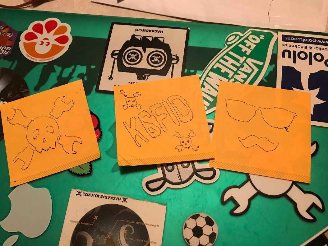
I decided to use 3″ square Post-It notes. The main feature is that they are self stick, so I don’t need any clamps or tape. It is also cool that you can stick them to things when the drawing is done. They are cheap and easy to find. I like the kind that have the majority of the back (full stick) covered in adhesive. This means you can use a small stack of them and peel them off as they are done.
Drawing Mechanism
I tried to make the drawing mechanism as tiny as possible. The size is about 30mm x 70mm. It uses (3) of the smallest readily available class of hobby servos call micro servos. You can buy these from AliExpress for as low $1-$2 in low quantities. The choice of the arm configurations was primarily based on tightly packing the the motors, but I also wanted something new and interesting.
The pen lift is simply a cam on one of the motors. The entire mechanism rotates on two 3mm bearings. In my experience with drawing machines, gravity is the best way to engage the pen to the work. The mechanism needed to work hanging from a lanyard or sitting on a table.
Electronics
There is only one electronic item right now. It is an ESP32 dev module. There are also (3) connectors for the servos and (1) for voltage monitoring. The entire back of the badge is a PCB. I made the board full size to enclose the back and the pen lift cam need to push on something. I have big plans for the rest of the area though. The ESP32 provides the Bluetooth and Wifi needed for the remote control.
Firmware
It is running my ESP32 port of Grbl with a little hacking for the servos. The ESP32 uses an RTOS, so I just created a low priority, repeating task (20Hz). The task checks the position of a virtual CNC machine, does some kinematic math and updates the servos. The software supports streaming drawing data (gcode) via serial port, bluetooth, SD card or wifi. I am using the bluetooth option to send via my phone. I will publish the firmware soon.
Crazy Math (Kinematics)
The math is actually not too hard. You know the desired pen location, the axes of the servos and the lengths of the linkages. There are two ways to do the math. The first way is using the law of cosines and the Pythagorean theorem.
The second method uses intersecting circles. Each linkage can sweep a circle from a axis point and radius. Any two linkage’s circles will intersect at two points. It is easy to pick one of the points as more desirable. While it is less deterministic, due to the two points thing, it appears to run about 40% faster on the ESP32.
The Z is very simple. Any Z value less than 0 is pen down and everything else is pen up.
Drawing Quality
The quality is basically “Adorably Wiggly”. I am using the cheapest analog servos. That means I might get about 200 x 200 resolution at best at the servo hubs. If you mapped that grid to the paper it would be a warped grid with dense and sparse areas of the grid due to the non-linear nature of the mechanism. Digital servos with very low deadbands (~1us) it would probably do a lot better, but I am not sure that is worth it. It would only be a little less wiggly. They cost about 4x what analog servos do (still pretty cheap).
There is a calibration feature. Each servo is a little different and it is difficult to precisely mount the arms at the right angle. The calibration adjusts the zero angle and pwm/degree of rotation.
Next Steps
This project is part of a talk proposal for Hackaday SuperCon 2018. If that gets accepted, the badge will become a full featured CNC controller capable of running a router, laser cutters, high res plotter, etc, as well as the Drawbot badge. Only the DrawBot will be populated. The rest will be modular like this board.
I may also make a simple version that is only the draw bot. The BOM cost is currently about $10-$12 (without 3D printed parts)
Regardless of what happens all source files will be publish sometime in October.
Follow me on Twitter (@buildlog) or subscribe to this blog if you want to follow the project.
If you want to be notified of future blog posts, please subscribe.
These are the basic instructions for setting up and using the Grbl_ESP32 CNC board. This is an open source CNC controller. It is for sale on Tindie. The source files are located here.
Program the ESP32
It is always best to program a CPU for the first time not mounted to a board. You don’t know if the current firmware will cause harm in the new application. A simple blink program could damage an I/O pin if that pin is tied to ground or a voltage when mounted.
Setup the Arduino IDE
Get the latest Arduino IDE from arduino.cc. (important…the latest)
Using the board manager and other tools menus select the board you have (see below for what options to set.)
Download the Grbl_ESP32 firmware from the GitHub repo. The master branch is generally more stable, but other branches will have the latest features.
Connect the ESP32 board to your computer via USB
Select the com port associated with the ESP32 module you have
Compile and upload the code.
Configure Grbl_ESP32
Now that you know you have everything setup properly to program the ESP32, it is time to configure Grbl. There are only (2) files that typically need to be edited. The defaults should work in many cases, but it is good to know what options you have.
cpu_map.h – This is the file that tells the firmware how the I/O pins should be used. The defaults will work with this board without changes.
config.h – This has dozens of things you can change. The defaults will work, but other features may interest you. There are lots of comments in the file to help you understand them.
If you made any changes, compile and upload the code again.
Install the modules into the controller board
ESP32
Disconnect the USB and install the ESP32. Be sure the USB is aligned with the edge of the board and the pins are perfectly aligned with the holes.
Motor Drivers (DRV8825 Recommended)
Make sure they are installed correctly. (2) of the pins are labeled, match them up with the same labels on the drivers
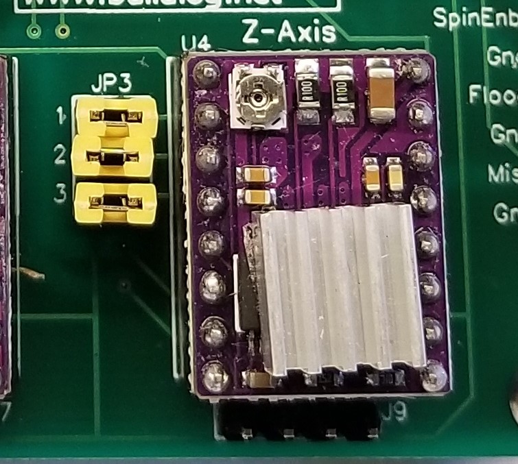
Set your micro stepping level according to the driver specifications. (DRV8825) using the jumpers provided. The jumpers are labeled (1,2,3 to correspond with the labels on the drivers. See image below)
Temporarily connect power (12VDC to 24VDC) to the board and set the current for the drivers. See the driver specifications on how to do that. They work well up to 1A without active cooling. They are set much higher by default and will generally have problems, so you should adjust them
SD Card
Install the SD module. Align the pin labels with the module and controller board. Note: The controller board has vcc labeled as 3.3V. It is actually 5V.
[image – Microstep jumpers]
Connect your motors, switches, etc.
If you need connectors, I recommend this set. It is low cost and will cover many projects. You can crimp the pins with needle nose pliers, but a crimping tool makes faster and better crimps.
Motors
The motor coils are connected to adjacent pins. A typical (but not always) motor wire color order would be red – blue – black – green.
Limit/Home Switches
Wire these as normally open and close to ground. Each switch has its own ground connection on the board to make things easier.
Control Switches
They wire the same as the limit switches, except the door should be a normally closed to ground. The door pins are connected with a jumper by default for people that don’t use the door feature.
Spindle
The Spindle PWM controls your spindle speed. If you want to run an on/off rather than variable speed spindle, just change the max RPM to 1. This means any RPM value with be full on. This is done via the $30=1 command. Note: Never connect these pins directly to a spindle or relay (non solid state). It is a very low current 3.3V TTL signal that must be connected to a speed control device or TTL relay driver.
Spindle Enable & Direction – This is not supported at this time, The I/O pin is used for the SD on the default firmware.
Flood Coolant – This is a 3.3V TTL signal to control a relay via the M8 command
Mist Coolant – This is not supported in the default configuration. The I/O pin is used for the SD card on the default firmware.
Many of the settings can be adjusted with $ settings. You can see what the codes mean here. Send $$ to see the current values. Send $xxx=xxx to change one.
Motor Direction – Try jogging the motors. If they go the wrong way your can either spin the connectors 180° or adjust the $3 value in the $$ menu. You should always remove the power if you disconnect motors. The drivers can be damaged if connected while power is on.
Tuning motor speed – By adjusting motor acceleration you can see how fast your motors can go with your setup. I like to see how fast the can go unloaded and then use about 75% of those values.
Homing (optional, but highly recommended)- Enable homing with $22=1. Switches can be put at either end of travel. Try homing. If any axis does not move towards the switch, you can switch the homing direction with $23
This is development board for using CNC on Grbl ESP32. It supports all of the current and planned features of Grbl_ESP32. It is a great way to get started with the firmware. It is currently for sale in my Tindie shop.
ESP32 brings the following benefits Grbl
Small and very low cost
Powerful dual core processor running at 240MHz per core
4MB of flash RAM
Floating point coprocessor
On board Wifi
On Board Bluetooth
Features
A very modular design – If any of the major circuits get damaged, you can plug in a new one.
A socket for a ESP32 Dev board also known as NodeMCU 32S. Most 19 pin per side dev boards should work, just check the pins or ask me.
(3) Sockets for stepper motor drivers. These fit many types of drivers. The TI DRV8825 type is my favorite driver for this type of application. Micro-step selection jumpers are included.
Home/Limit switch connections for XY and Z axes. These also have R/C filters to eliminate high frequency noise from false triggering the switches.
Z Probe connections with R/C filter
Control switch input connections for Feed Hold, Cycle Start, Reset and Door. These have filters as well as pullup resistors, because they are on inputs that do not have internal pullups.
Spindle output for PWM (Speed). Spindle Enable and Direction are also connected, but not in firmware yet.
A socket for a micro SD card module. Note: The SD card feature is in testing and not in the master branch firmware yet. Also it shares pins with other non-popular features that would have to be turned off (Mist Coolant, Spindle Direction and Spindle Enable)
DC-DC power supply. There is a strong 3A DC-DC power supply to run the ESP32 if it is not connected to USB. It is adjustable, 0.8V to 20V, but would typically be set to 5V. It also has connections, for off board use.
The SD Card pin 5 (vcc) was accidentally hooked up to 3.3V. It should be connected to 5V. The boards have a simple cut and jump. Keep this in mind if you use the gerber files.
Where to get one
You can build your own from the source files or you can buy one from my Tindie store. Buying one from me helps support this project.
If you want to be notified of future blog posts, please subscribe.
Here is a look at something I have been working on. I have added some SD card features to Grbl_ESP32.
Why SD Cards?
Grbl works great with senders and really shouldn’t need SD card support. That is true for your typical desktop CNC router. laser, etc., but there are a lot of machines that are not “typical”. I like to make machines I can fit in my backpack or in the palm of my hand. I certainly don’t want to use a traditional PC – Machine setup. I want control via phone or completely autonomous. This means SD card, Bluetooth and Wifi options are critical.
Does a machine even need connectivity at all? Running a file from an SD card and uploading new firmware via SD card is going to be critical for some new projects I have plans for.
What is the best way to do this?
After debating a few methods of implementing this, I decided to do it in a more Grbl’y way, than a Marlin’y way so that it is less likely to break the existing Grbl gcode senders. This means I’ll try to report status and push notifications in a way that won’t break anything. I’ll also follow the strict NIST gcode rules of Grbl. NIST does not have SD gcodes, so they will be more like Grbls $H (homing) than Marlins equivalent gcodes.
With that said, if anyone has some suggestions for changes, I am still in a stage where I can consider them.
Protocol
The commands all start with $F (for file).
$FM – Mounts the SD card. You do this once whenever you want to use the SD card or after you re-insert.
$F – Reports all the files matching (.NC, .TXT or .GCODE). It printrs one line per file like [FILE:/myfile.nc SIZE:7609]
$F=/myfile.nc – This runs the file.
Job progress is automatically appended to the end of the “?” command response. like <…….|SD:55.78> where 55.78 is the percent complete.
Sender Compatibility
All of senders I have tested (UGS, LaserGrbl, Grbl Controller) are OK with these changes.
They continue to request and get status and update the DROs.
If they have a verbose option, you can see the job progress.
Some (Grbl controller) filter out (don’t display) the [FILE:….] responses even on verbose mode.
All can be disconnected during a job without affecting it.
Most send a Grbl Reset when reconnected which kills the job. This would be easy to ignore during SD card jobs (not implemented).
Next Steps
I will release a branch with these features
I want to look at adding a card detect feature to auto mount the card
Look at methods of firmware upgrade via SD card.
Can a file be uploaded to the SD card (USB, Bluetooth, Wifi)?
Video
If you want to be notified of future blog posts, please subscribe.
After a lot of work and testing, I have posted the firmware to GitHub. I have a good write-up on the process I went through to get to this point on this blog post. There are some basic getting started instructions on the GitHub page. Realistically, this probably should not be your first Grbl or ESP32 project, but go ahead if you like.
If you want to keep up to date on the project, subscribe to this blog (see end of blog), subscribe to my YouTube channel or follow me on Twitter (most frequent updates). Comments, thumbs up, retweets and replies are very much appreciated and keep me going.
If you see any issues, please comment here or at GitHub. GitHub is preferred for firmware issue tracking.
BTW: If you are interesting the test controller I made, here is a schematic.
Next Steps
I have a busy couple of weeks coming up with some friends coming from France to visit. I won’t be able to work on the project much. The first thing I want to add when I get a chance is BlueTooth support. If you know of any similar projects streaming text from a phone or PC to ESP32 over Bluetooth, please let me know.
Video
If you want to be notified of future blog posts, please subscribe.