Bluetooth Serial has now been added to the master branch of Grbl_ESP32. Bluetooth Serial means the Bluetooth connection looks like a serial port when you pair with the device. This is ideal because it allows all existing gcode senders that support serial ports to use Bluetooth.
This was added using the Bluetooth Serial library that is part of the espressif/arduino-esp32 development environment. This library is relatively new and has a few issues, but I was able to work around them.
Sending Characters: The reporting done by Grbl sends characters a character at a time. This means dozens of calls to the library are needed for each response. This caused characters to be dropped. The solution is to send a full string in a single call using .print(), rather than sending individual characters using .write(). Grbl was written using the character at a time method to highly optimize the reporting. The raw speed of the ESP32 does not require that optimization and the resulting code is much more readable.
No Password: The library does not support the use of a password for the pairing. This is a big drawback, and needs to be considered before you enable Bluetooth. Apparently this was due to an upstream component that has now been fixed. Hopefully it means the library will be updated soon.
Why and when to use it.
The cost, size and wireless features of the ESP32 are the primary reason I ported Grbl to the ESP32. I make a lot of tiny CNC machines. A laptop is likely to be many times the size of the CNC machine. I wanted to control the machines via a phone or small tablet. I have found the connection to be very reliable, even for jobs lasting more than an hour. The phone can even be in the “off” state in your pocket and it will still stream reliably. The battery drain is accelerated, but not significantly (like listening to audio via Bluetooth) You do need to stay within range of the machine, although Grbl Controller (Android) appears to be able to resume a job.
Using Bluetooth.
It is optional. You enable the feature at compile time. That allows you to save some code space (not really an issue now). Once the feature is enabled, you can still turn it on or off via a serial port command. All Bluetooth traffic is echo’d to the serial port. This allows you to monitor the communications. You can also use the Serial port at any time, but it is not a good idea to do that while running a job. Here are the steps to set it up.
Make sure #define ENABLE_BLUETOOTH is not commented out in config.h.
Use a serial port terminal to set the Bluetooth name using $I=NAME, where NAME is the Bluetooth name you want. I don’t know all the naming rules, so keep it short and simple. There is no capability to use a password yet. Grbl converts all input to capital letters, so lowercase will cannot be used.
Reboot the ESP32 to turn on Bluetooth with that name. Grbl will send Starting Bluetooth:ESP32BT as the first item when booting to let you know Bluetooth is on. ESP32BT is the Bluetooth name I used in this case. Grbl will now respond on either Bluetooth or Serial data. All Bluetooth sends are echo’d on the Serial port if you want to watch the data.
You can now pair a phone or PC with Grbl_ESP32.
Caution: Do not pair while running a job. The ESP32 will likely interrupt and/or watchdog issues while the stepper timer is running and the pairing process is running.
Next Steps
Other modes: A phone also makes an awesome display and control panel. Maybe the PC is the primary sender and the phone acts as a pendant.
SD card. SD card is next on the roadmap. This pairs well with bluetooth, because the phone could select and start an SD card job.
If you want to be notified of future blog posts, please subscribe.
After a lot of work and testing, I have posted the firmware to GitHub. I have a good write-up on the process I went through to get to this point on this blog post. There are some basic getting started instructions on the GitHub page. Realistically, this probably should not be your first Grbl or ESP32 project, but go ahead if you like.
If you want to keep up to date on the project, subscribe to this blog (see end of blog), subscribe to my YouTube channel or follow me on Twitter (most frequent updates). Comments, thumbs up, retweets and replies are very much appreciated and keep me going.
If you see any issues, please comment here or at GitHub. GitHub is preferred for firmware issue tracking.
BTW: If you are interesting the test controller I made, here is a schematic.
Next Steps
I have a busy couple of weeks coming up with some friends coming from France to visit. I won’t be able to work on the project much. The first thing I want to add when I get a chance is BlueTooth support. If you know of any similar projects streaming text from a phone or PC to ESP32 over Bluetooth, please let me know.
Video
If you want to be notified of future blog posts, please subscribe.
I have been working on this for months. I am happy to announce that it is finally working right. The ESP32 will be a great option for CNC. Here are some things I am excited about.
Fast – Two 32 bit Cores at 240MHz Each, FPU, 80MHz Timers
Memory – Tons of Flash and RAM
Low Cost – $3-$10 depending how you buy it.
Small Size – Not much bigger than an Arduino Nano
I/O – It has about the same number of pins as an Arduino UNO, which is the target for Grbl
BlueTooth and WiFi – This is great and actually the primary reason for my port.
Porting
The bulk of the code was very easy to port over, but getting very low jitter, step pulse timing took a long time to achieve. This is not my first port of Grbl. My first port was to the PSoC5. That was much easier, but this was my first major project on the ESP32.
A goal was to use the Arduino IDE to develop the code. I thought it would make the project a lot more accessible to novice programmers that just need to make a few tweaks. I also tried to make the code easy to maintain with Grbl. This means there a few throwbacks/workarounds to AVR port numbering. etc.
FreeRTOS
The ESP32 uses an RTOS (Real Time Operating System). While “real time” sounds perfect for CNC, it is not good for step pulse timing. An RTOS allows multiple tasks to run “at the same time” and it manages the priorities and interaction of those tasks. The RTOS switches tasks at a “tick rate”. The tick rate is typically about 1000Hz. This means each task gets at least 1ms of time and the others wait. You can designate a high priority task to prevent these interruptions, but some tasks have watchdogs that must be reset so you need to give them some time. You can set the tick rate higher, but I need a more than 50,000 hz step rate. That is not practical for the RTOS. I can turn off the RTOS and/or the watchdogs, but a major appeal of the ESP32 is the WiFi and BlueTooth. These need the RTOS.
Interrupts
The normal Grbl way generate step pulse timing is to use interrupts. As long as you follow the rules for interrupts, they will interrupt the RTOS without any delays in very deterministic manner. The rules are about how much time you can spend in the interrupt and what things you can do in the interrupt. The interrupt duration was not an issue because the code in the interrupt only takes a few micro seconds. What you can do in the interrupt took a while to figure out. The ESP32 does a “panic” reboot when it does not like something. That happened a lot during development. Most of my problems were related to how I used the peripherals. Things like the RMT feature simply can’t be used.
My Dev Board
I designed a little Dev Board to help me with this project. The features include…
3 Stepper Drivers
3 Limit Switches
1 Touch Probe connector
Mist / Flood Coolant outputs
Start / Hold / Reset / Door switch connector.
Spindle / Servo / Laser – Connector
SD Card – This is just a breakout to a header that can be wired into the CPU if I ever decide to do that.
Next Steps
Testing – I need to do a lot of testing. I tested most of the features along the way, but need to double check all the config options.
Clean up – I have a lot of commented out debug code that needs to be removed
BlueTooth – That is the first new feature I want to add.
Hobby Servo Features – I use them a lot in my small machines and 328P Grbl doesn’t handle them well because the lack of 16 bit timer availability. I want high resolution jitter free servos as an option for any axis.
Simple Kinematics – GCode can be converted on the fly to alternate coordinate systems. This would not consider joint dynamics.
Video
If you want to be notified of future blog posts, please subscribe.
I added native USB support to my PS0C5 port of Grbl. The PSoC has USB capability on the chip. It also has a component for using it as a USB UART (CDC Interface). This means it looks like a serial port to the connected PC and uses the standard CDC interface driver that most OS have.
I am currently only using this on the PSoC5 development board so I am comfortable using their VID and PID values. If I make some custom hardware and distribute it, I will need to get my own.
Advantages
Low Cost – You don’t need to buy a separate USB/TTL chip
Faster – It should be able to run a lot faster. You can select any baud rate you want. It never converts to TTL I think the rate is meaningless. I am not sure if it translates to actual fast jobs, but it might on data heavy laser type jobs where the laser power level is changing a lot.
Compatibility – It still looks like a UART to senders, so you can use all existing senders.
Future Features – It might be possible to have the USB look like multiple features like a memory device, to make file transfers possible.
The Code
I put it in a separate repo from my last code. I started with a more recent version of Grbl, plus I removed the LCD code. I typically don’t use the LCD and prefer a serial/bluetooth remote. It could be easily added back in from the original port.
To do list?
The USB is checked for incoming data in the protocol_main_loop(). Is there a way to do this with an interrupt?
Arduinos have a DTR triggered reboot. Some senders expect this. Can we emulate this behavior?
I want to add SD card support to Grbl
Then try to make that accessible as a USB drive.
Help?
If you want to help, just let me know via comments below or on the GitHub page.
If you want to be notified of future blog posts, please subscribe.
The NickelBot has been running great, but there were a few features I also wanted to add. I made a rev 2 PCB to address them.
Laser Door Interlock
There is a door switch that cuts power to the laser. I did this by splicing into the 12V power line going to the laser. I thought that was an effective, but ugly hack. There is now a dedicated connector for that switch.
Fan Control
On rev 1, the fans run continuously. This reduces my run time, when I run off a battery. I added a FET to control the fan power. I want the fans to turn on whenever the laser fires and stay on for a few seconds after the last pulse. Since the controller is a PSoC, I was able to implement this as a custom hardware peripheral. I used my pulse extender component.
Here is the schematic. The trigger is connected to the PWM signal going to the laser (labeled spindle). There is a 16 hz clock that is used to count down a short delay after the last pulse.
BlueTooth
Using a connected computer sort of spoils the coolness of these tiny machines. Using a phone and BlueTooth is way cooler.
Most of my other tiny CNC machines use BlueTooth. I don’t know why I forgot it this time. It is the first time using an HC-05/HC-06 bluetooth adapter with PSoC, so that might be the reason. I decided to use a second UART, so I could use both USB/Serial and Bluetooth at the same time. The changes to firmware where pretty trivial.
Grbl Controller Shout Out
The main Android phone app I use is Grbl Controller. It really works great and is so easy to use. It works great with the cheap HC-05/HC-06 BlueTooth adapters. I just send gcode files to my phone and run them from there. I can even turn the phone “off” and stream from my pocket.
If you want to be notified of future blog posts, please subscribe.
The NickelBot is complete and it works great. The goal of the project was to create an easily portable machine that creates low cost items that could be given away at events like Maker Faires. I think it has completely achieved that goal. The nickels are purchased from Amazon and cost about $0.08 each.
Here is a video that explains the machine.
Results
It is quite reliable and the cycle time is is just about right at 1-2 minutes per nickel. I think the engraving quality is quite good. I ran it at the Chicago Northside Maker Faire last weekend. It made about 60 nickels without any problems. Here are some of the nickels it made.
Mechatronics
The NickelBot uses (2) NEMA14 stepper motors in a T-Bot configuration. These drive a single GT2 6mm belt. The linear bearings are (2) 6mm rods per axis with (1) LM6LUU per rod.
To handle the nickel loading and unloading, it uses a single micro hobby servo. This servo connects via a 0.03″ brass wire to a clamp. The firmware has (3) positions hard coded for the servo for fully open, nickel support only and supported plus clamped.
All 3D printed parts are PLA printed on a Lulzbot TAZ6. The colors just represent the color that happened to be in the printer at the time.
The Laser Module
The laser module is a 3.5W peak, 450nm (blue) laser. It comes with a laser power supply that has a 12V power input and TTL laser control input. It also comes with a 12V 5A power supply. I bought it a few months ago from Banggood.com when it was on sale for about $70, but they are typically around $99. I control the engraving power with a 5kHZ PWM from the microcontroller.
Controller
I used a PSoC5 development board as a plug in on a custom PCB. I knew adding an additional, accurate PWM for the servo was going to be vastly easier on the PSoC5 vs. an Arduino.
This dev board has a built in programmer debugger that makes firmware development very easy. It is great to be able to set breakpoints and check values with the debugger. I have have a another blog post with more details on this here.
Firmware
The firmware is a modified version of my PSoC5 Grbl port. The only modification needed was the code to handle the clamp servo. Rather than adding special gcodes for the clamp, I simply re-coded the M7,M8 and M9 coolant commands. I did this because all of the parsing and protocol issues were already done. Each command represents one of the clamp positions.
I may post the source code on Github soon.
Calibration
The machine has (2) home switches (X and Y). A homing sequence needs to be run each time you power up the machine. All other locations are referenced to this location. A one time calibration is done to locate the following locations.
G54: G54 is the the default work offset. I decided to use the center of the nickel as the 0,0. I jogged the machine visually until the nickel looked centered. I then set the G54 location with this gcode line”G20 L10 P0 X0 Y0″. I made a target shaped graphic that I used to test engrave this location(see above). I used a caliper to measure the centering error, jogged that amount and reset the 0,0. I did this about 5 times until I was satisfied with the centering.
G28: I used the G28 location as the location under the nickel hopper. You jog to the location and set it with “G28.1”.
G30: I used the G30 location as the position over the eject chute. This is set with the G30.1 gcode command.
This is a great program for this application. It does everything, starting with a bitmap image, to gcode sending in one application. It also has some macro (multi-line gcode) buttons that are very handy. The only drawback for some is that it is Windows only.
Here is an example of the macro to get the nickel.
G90G0X0Y0 ; rapid move to absolute 0,0
M9 ; loosen clamp
G28 ; move under nickels
G4 P0.75 ; wait for nickel to fall and settle
M7 ; close clamp
G4 P0.5; wait a bit
G0X0Y0 ; return to 0,0
Interlock switch: Right now there is no interlock switch for the door. If I make a new PCB, I will add a provision for that. I’ll probably just break all power to the laser module.
Nickel Flip: Right now the nickel always comes out of the chute upside down. This is not the best presentation. This was a compromise to make the machine as small as possible. The nickel has to fall between the Y rods. Rather than makethe distance between the rods wider than the nickel, I designed and aligned the clamp/support system so that one side of the nickel falls first and goes between the rods closer to vertical. There is a probably a way to design the chute to catch the nickel before flips over completely or re-flips it back.
Software:
More automation: LaserGRBL has macro buttons for the nickel feed and eject features, but it would be nice if that was automatic. They have added a gcode header and footer feature to the roadmap. Right now you can generate the gcode, save the file and paste the nickel handling code in an editor. That file is then fully automatic.
Customizing: It would have been fun to easily add names, etc to nickels for people.
If you want to be notified of future blog posts, please subscribe.
Here are some details on the custom laser controller I made for the NickelBot, wooden nickel engraving machine.
I want to use Grbl to control the machine. Grbl has support for lasers that allows better power control during the engrave. It also has the Core XY support I need for the H-bot mechanism it uses. The only feature I needed that it did not have is a hobby servo output.
A hobby servo requires a PWM signal. Normal Grbl runs on a ATMega328p cpu (Arduino UNO). The 328p has 3 timers that can be used to generate PWM signals. Grbl uses all 3 of them. You can attach more than PWM output to a timer, but the only timers that would work are only 8 bit timers. That is not going to give me the resolution I want.
A hobby servo uses a 1ms to 2ms pulse that repeats every 20ms. This means you are only using 1/20th of the duty cycle range. 1/20th of an 8bit signal is pretty rough. I could have used an Arduino Mega to get some more free timers, but I did not want to deal with the physical the size of a Mega.
My solution was to use a PSoC5. I have already ported Grbl to it and it has plenty of high resolution PWM components. I used the following PWM configuration…
16-Bit resolution
1 MHz Timer
20000 for the period (=20ms)
1000 to 2000 and my compare value range (1ms to 2ms)
This gives me a resolution of 1000 or 0.18° (exceeds servo’s capability)
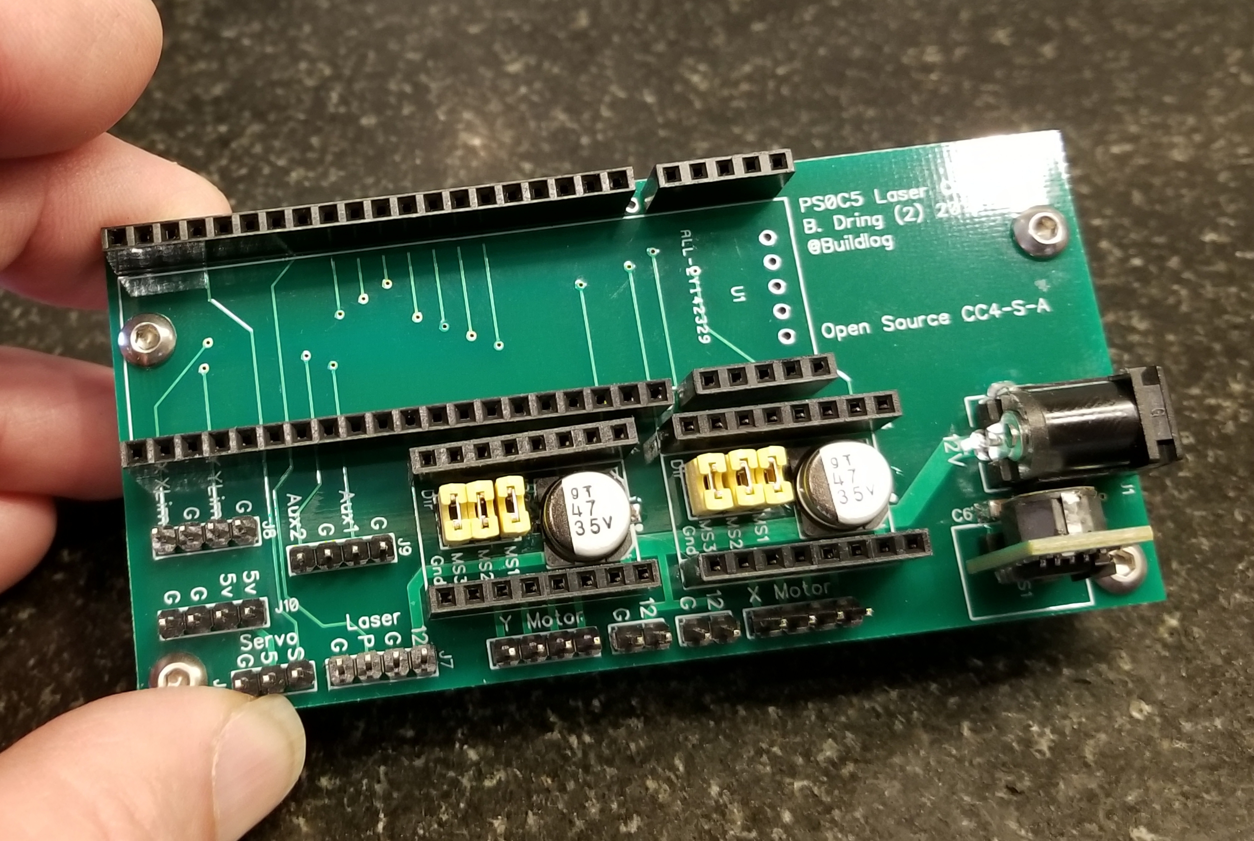
Here is an image of the raw PCB.
Here are the features of the PCB
Has a socket for a CY8CKIT-059 PSoC5 development board (only $10-$15). The only drawback is the wiggly printed USB connector.
The board is fully tested and 100% functional. I have it hooked up the the machine and have tested the following.
Home switches
CoreXY motor control
Servo control
Laser PWM.
Fans
Suggested Changes
The control signal on the laser supply appears to turn on the laser if left open. Therefore if the controller is not powered or actively driving the pin low, the laser will fire. That is not good. I have not tested a solution, but I think a resistor of 2k-5k Ohm pulling the pin to ground will keep the beam off when not driven low. It should be quite easy to solder this resistor between the laser pulse pin and the adjacent ground pin.
If you want to be notified of future blog posts, please subscribe.
I got a chance to do some work into this project and I made some progress.
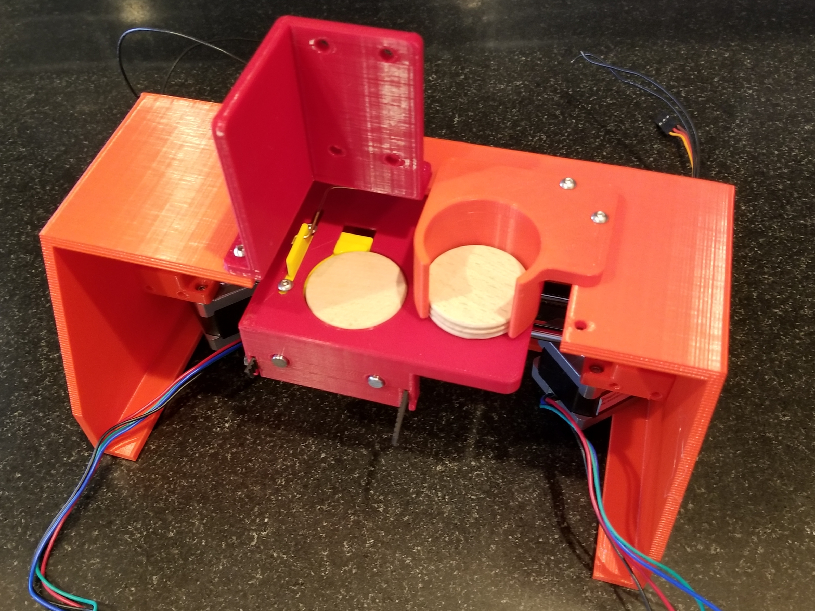
The X,Y mechanism is a free standing H-Bot. Here is a bottom view. You can see the Y home switch and the bottom of the servo to control the nickel.
Here is a top view of the mechanism. The yellow clamp piece opens partially to create a platform (ledge) for the nickel. This slides under the nickel feed tube and a nickel drops in. The bed is extra wide, so there is always something supporting the nickels in the feed tube.
The servo then clamps the nickel by pushing the tang on the yellow clamp piece into the nickel. Once the engraving is complete, the clamp completely retracts, removing the ledge. The nickel falls through into a hopper that is accessible from the front. This allows for a fully automated process and you don’t need to open the machine.
Here it is with a nickel in the clamp.
I have a temporary enclosure for testing. This supports the XY mech. You can see the nickel feed tube and the laser module support bracket. Currently it is open and a little larger than necessary to make it easy to test. It will eventually be cleaned up and get an access door with a window.
The next step is to work on the firmware. I plan to use Grbl in Core XY mode. I need to add a way to control the servo and figure out some commands to control the nickel handling.
If you want to be notified of future blog posts, please subscribe.
The first step is to program your ESP32. The kit I sell on Tindie requires the use of the NodeMCU-32s. It needs to match this footprint and pinout. Note: Some version of my kits include a pre-programmed ESP32.
Arduino IDE Setup
You need to compile and upload the firmware using the Arduino IDE. Get the latest version here. You need to add some additional software.
Install Arduino Core for ESP32. This gets the files require to program an ESP32 There are instructions here.
Install FastLED Library. The FastLED library is used to control the LED strip. Go to this page and download the latest version as a zip file. In the Arduino IDE select the Sketch…Include Library…Add Zip Library. Then select the zip file you just downloaded.
Install RunningMedian Library: This library is used to filter (reduce noise) the accelerometer sensor using a 5 point median filter. You can get the library here.
Open the TWANG32.ino sketch in the Arduino IDE you will see this near the beginning of the file…
// what type of LED Strip....uncomment only one
#define USE_APA102
//#define USE_NEOPIXEL
You need to uncomment (remove //) in front of the line for the strip type you have. In the case above the program will compile for the APA102 type strips. Make sure only one of the #define lines is uncommented.
Open the settings.h file in the same folder as TWANG32.ino. Change the #define NUM_LEDS 144 to the LED count you plan to use. This sets the default number of LEDs in your strip.
Next to the following steps to compile and upload the firmware. This could take several minutes to compile.
Under the Tools…Boards menu, select the NodeMCU-32S board
Connect the ESP32 to your computer.
Select the correct com port from the Tools…Port menu.
Click on the Upload button.
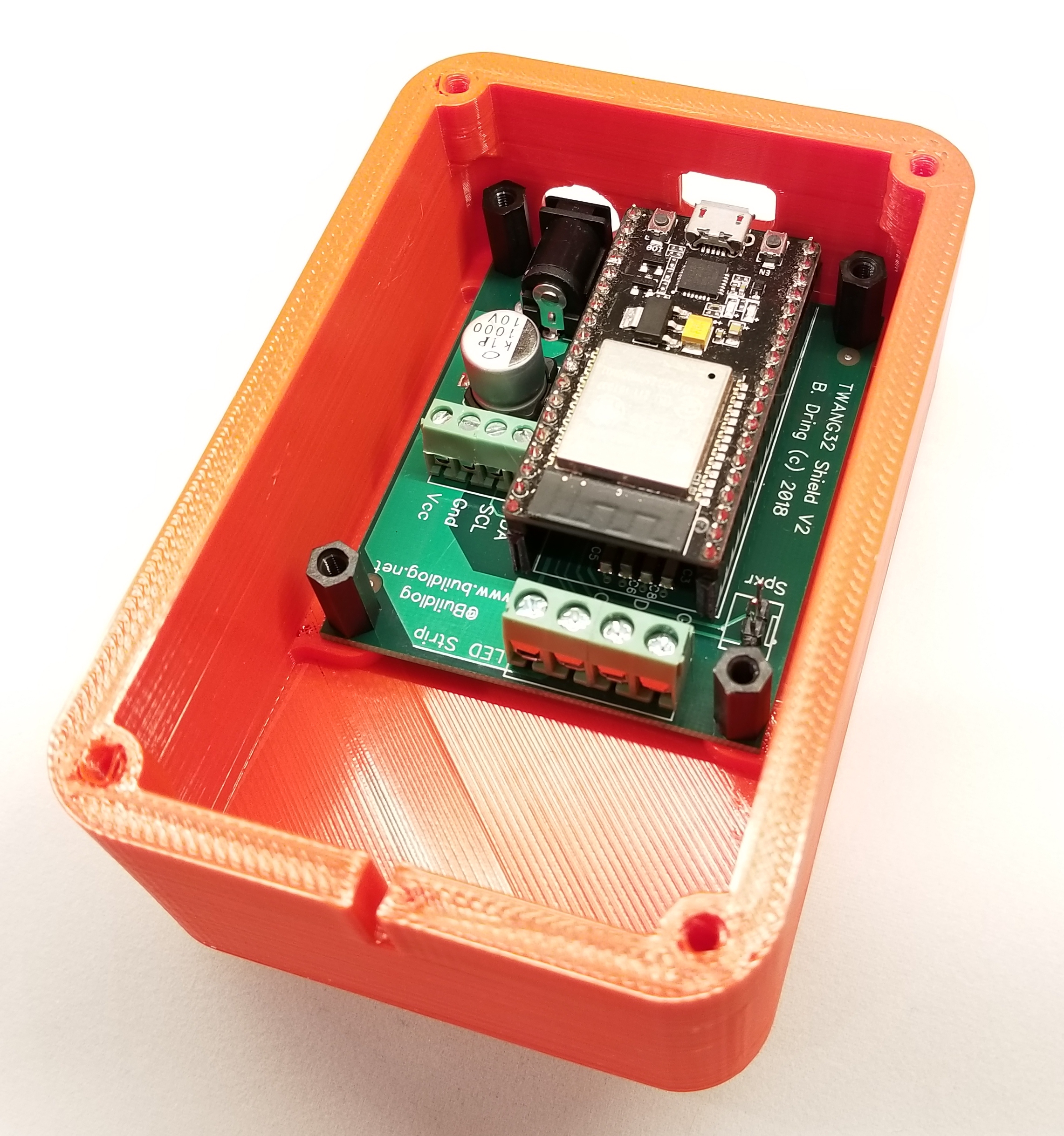
Install the ESP32 in the PCB.
The ESP32 should be installed with the USB connector aligned with the edge of the PCB. See the image below.
Print the plastic parts
The STL files are here. If you don’t have a printed, reply in the comments and I can get you some for a reasonable price.
All of the files can be printed in high speed mode. No fine details are required. They can all be printed with no support, except for the cover which has a small pocket on the bed side. I use PLA with 2 perimeters and 20% in fill. All of the screws self tap into the plastic.
Note: I made a recent change to eliminate the use of hot glue, some of the pictures are from earlier versions.
Attach the Adhesive Rubber Feet to the Chassis.
Attach the feet into the pockets on the bottom of the chassis.
Install the PCB into the chassis.
The PCB mounts directly on the bosses on the bottom of the chassis. Use flat head M3 x 12mm screw installed inserted the chassis bottom, through the PCB and into M3 x 12mm plastic spacers. Spacers are easier to use than nuts because they are easier to hold during installation.
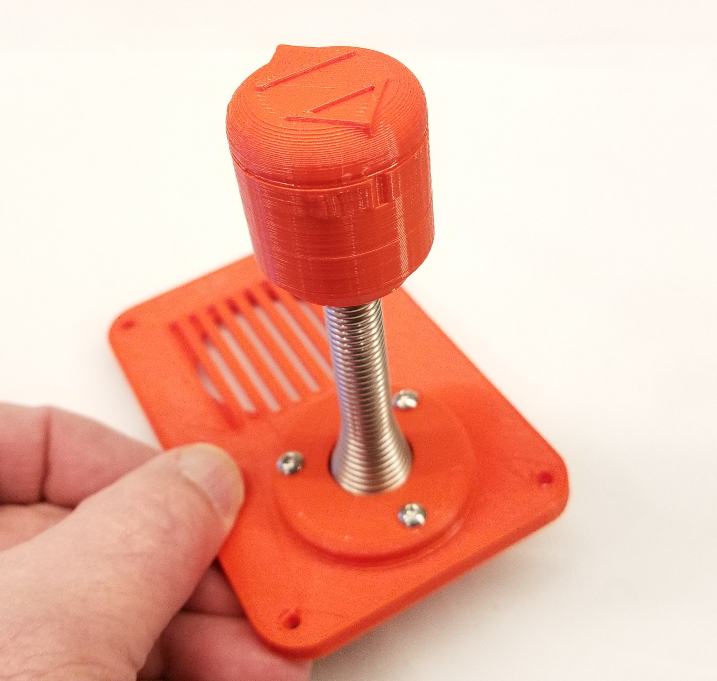
Assemble Joystick.
Place clamp ring over door spring. It is important to do this first because it is difficult to do later. Next screw on the the lower part of the knob.
Slide the accelerometer module wires through the lower knob and spring. Push the accelerometer module into the pocket. I have recently made changes to remove the need for hot glue. This uses M3 x 10mm (button or pan head) to hold on the cap. I use a little piece of anti-static foam (in kits) to hold the MPU-6050 accelerometer module down. If you don’t have the foam use 2 dots of hot glue in the corners with the mounting holes.
Attach the cap. Align the hollow arrow side of the cap with the little notch at the top of the lower knob. This hollow arrow will show you which side points forward in a later step.
Attach the metal cap to the bottom of the spring. This cap allows the spring end to sit flat on the cover. It should be screwed on about as much as shown in the image.
Attach the joystick to the cover. Make sure the hollow arrow is pointed forward (the closer edge). Before it is fully tightened twang it a few times. This will relax the spring so you can see if it still points forward. Do this a few times and adjust to make sure it points forward. It does not need to be perfect… +/- a few degrees is OK.
Attach the speaker using M3 x 10mm screws. If you angle the wires a little, it makes the wiring a little easier later.
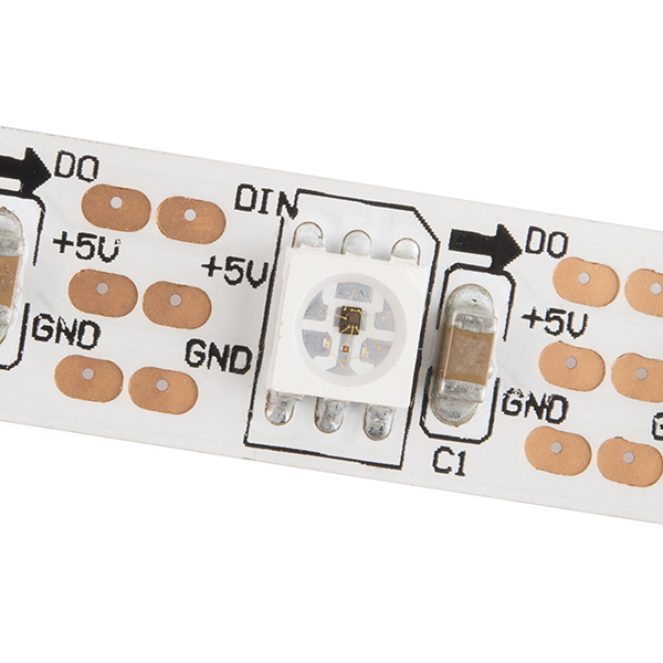
Attach the LED cable. Your LED strip should have come with a mating connector. Some types have 3 wires and some have 4. Mate it to the LED strip. See what colors do what functions by looking at the strip labels. The strips have an arrow pointing the ways go from zero up. Most strips have connectors on both ends. Us the connector on the base of arrow side.
All LED strips should have a + and -. These could be labeled 5V and Gnd. Do not rely on the traditional red+ and black- wire coloring. The strips are often not wired that way. Attach the wires to the terminal block. I like to add a cable tie behind the wall to act as a strain relief. I also label my wires, but you need a heat shrink printer for that.
Attach the rest of the wires from the cover. Attach the speaker connector and the accelerometer wires.
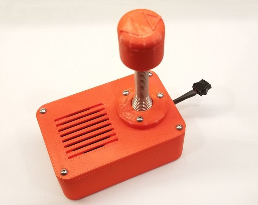
Attach the cover.
At this point you should be able to power up and play.
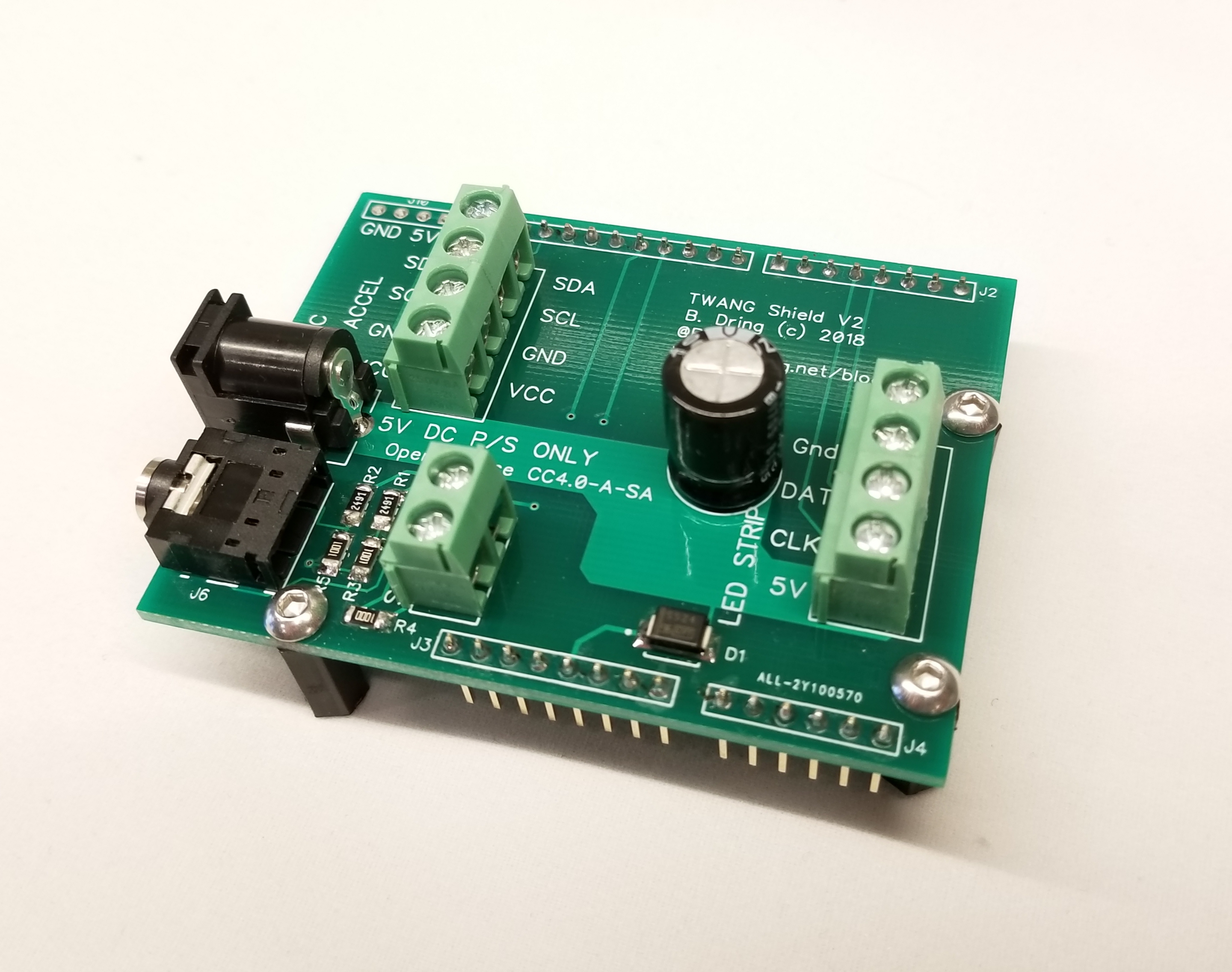
I recently ran out of the original TWANG shields. I took the opportunity to make a few changes.
Audio Jack
The internal speaker is powered by the Arduino I/O pins. This limits it to the low voltage and current that those pins can provide. In normal environments that sound has plenty of volume. I have used it at some very loud events where that sound level is not loud enough.
This version adds a standard 3mm (1/8 in.) audio jack. You can connect this to a powered, external speaker.
Power Capacitor
Some old LED strips like the WS2812 are very sensitive to voltage spikes that might come from lower quality power supplies at turn on. They recommend adding a large capacitor to reduce voltage spikes. A larger 1000uF capacitor has been added to the PCB, so you do not need to install it externally.
Life LEDs
The TWANG firmware supports the use of remaining life LEDs. The firmware normally shows the remaining life LEDs on the LED strip. This has the advantage of making it easy to change the lives per level without having to change your hardware. On version 1, there was a place to install (3) life LEDs, but the LEDs were never installed. This version removes that feature.