I thought I had it cracked, turns out I need to go back to the drawing board to fix backlash issue in the y-axis. So this will be my build thread as I attempt to integrate ballscrews into my design and get the backlash down to a usable level.
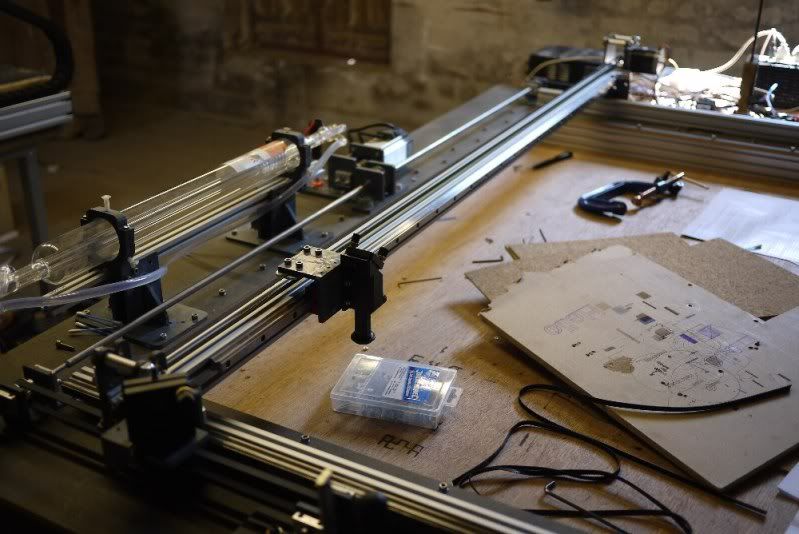
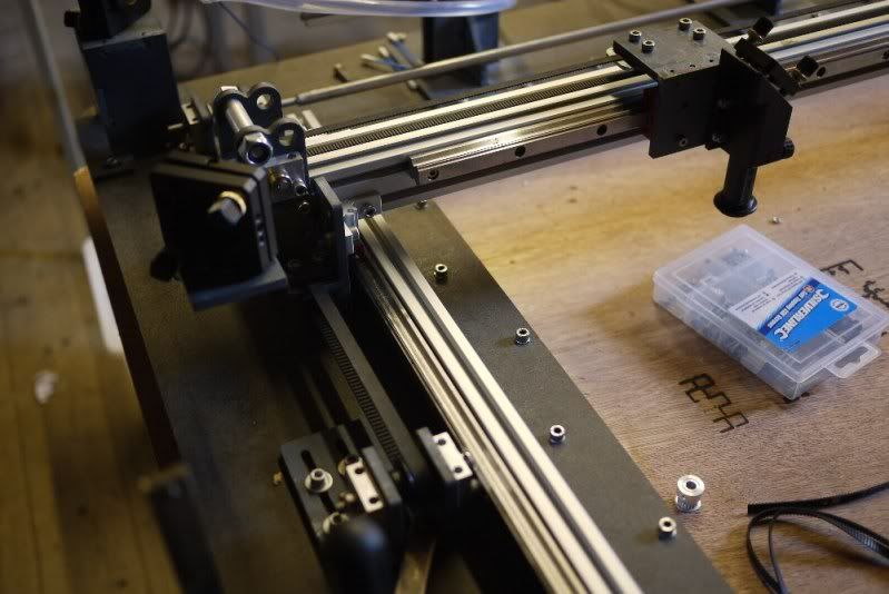
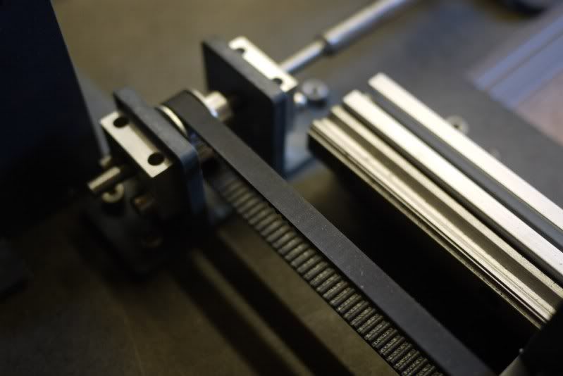
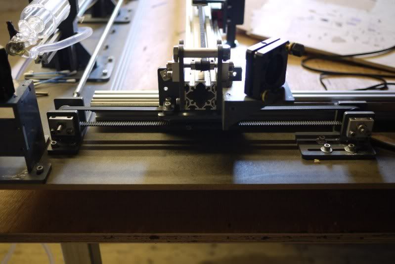
I am building a 40w 1.2m*0.9m laser cutter with servo motors and a Lightobject dsp.
Here are a few pics of the laser setup with the old y-axis HTD 3mm belts. The run of belting was chopped down to about 300mm as a test to see if it would reduce the backlash, which it did suggesting it is possibly belt stretch
Comment from: iGull on Thursday, May 24th 2012 - 8:26 PM
gavztheouch wrote:Here are a few pics of the laser setup with the old y-axis HTD 3mm belts. The run of belting was chopped down to about 300mm as a test to see if it would reduce the backlash, which it did suggesting it is possibly belt stretch
Hi Gav
Worrying, that's a similar type of belt I'm using (from motionco - HTD 9mm wide 3mm pitch , aluminium pulleys). After replacing my slotted shaft couplers for the same ones you are using (marchantdice), my backlash virtually disappeared. I say disappeared in the loosest sense, there is obviously still some, but it's barely visible (it's measurable of course- approx 0.1/0.2mm 'ish). To be honest, visible is more important to me than measurable these days as I no longer build parts for the hubble
I'll follow this new thread with interest, are you considering trying HTD in a different type of material? If so, then I'd be interested in any improved results (so I can change mine if it works, or let you spend the money if it doesn't )
Ballscrews should prove interesting, high helix screws are certainly not cheap, and in the size you need, they'll need to be rigid - you won't get away with little teflon coated jobs at 6mm diameter and 20mm pitch I'm guessing min 15mm in X?
Good luck with the mk2, it's looking good. I do fancy another build, slightly smaller perhaps (700-900mm X) and with decent quality slides like yours. I have a huge THK linear slide sitting in the garage, but it's just too hefty for a laser - more suited to that heavy duty cnc router.
Cheers
Neil
Thursday, May 24th 2012 - 9:39 PM
Motionco HTD 9mm wide 3mm pitch that's the very same, I got my pulleys from there as well.
Im thinking of giving it one more go with the belts, this time I will use some aluminium for the pulley supports and bolt them onto the side of the Misumi extrusion instead of my rather woolly 9mm MDF top. This should stiffen the assembly up and take some of my worries about the chassis flexing under load away.
Currently, to tension the belts I am only using my hands and a screwdriver as a lever to pull back the idler pulley and then lock into place once I have moved it far back enough. Do you think it is possible to get enough tension in the system using the method, to give you an idea of how tight the belts are if I pluck one it rings like a guitar string, but with the motor locked I can still move the carriage back and forward as the slack is taken up. I like the way Maralb (a poster in this forum) uses a simple screw system to tighten his belts.
I have found some ballscrews from Zapp automation that have a lead of 20mm and a diameter of 15mm these look perfect for the job and cost around ÂŁ80 plus ÂŁ65 for the ballnut each. Then you need support bearings, about ÂŁ100 for enough for both screws. So around ÂŁ400 with delivery, a lot really, and more than I can currently afford right now.
Another issue with the ballscrews is if one of my motors takes a flaky and takes off on its own, it will cause the gantry to twist and no doubt break something, if not bend the critical x-axis extrusion. To that end I will prob need to look at linking the two motors together with a chain or belt.
Just to add, I recently read about a belt driven router that had a backlash figure of something like 0.003mm. I know it is possible, its just a case of time, money, and know how all of which I need to acquire.
Comment from: iGull on Friday, May 25th 2012 - 8:00 AM
Had a quick look at the belt specs - not that much info really - mine aren't overprinted with a manufacturer. As far as I can see on their site, tension should be 100N. Without getting involved, let's call it 10Kg or 22lb if you are metrically challenged. That should be easy to pull by hand without resorting to a screwdriver lever Similar specs at gates show +\- 0.03mm at 1200mm belt length variation (I'm assuming manufacturing variation). As for stretch, I don't know. Perhaps someone with higher mechanical knowledge can suggest what a ballpark value might be for HTD 3M style (not the company) 9mm wide, 3mm pitch. I believe the core is glass with neoprene casing - maybe kevlar is better (although I can't think why kevlar would stretch less than glass). As an aside, gates have a wee tension gadget where you pluck the belt and it listens for th tone - you put in some values and it tells you what tension is. I have an app (free I think) on my iphone that I use to tune my guitars, maybe that would work - given a similar overall length ? Need to ask the guys at motionco methinks.
BTW, locking your two Y leadscrews together when both are being driven is not a great idea. However, driving one and belt to the other is ok - but you're then back at square one Its really only a problem when one fails (note the word 'when' . I know of lots of systems that use two motors 'though - shopbot springs to mind.
Cheers
Neil
Monday, May 28th 2012 - 12:45 PM
As far as I can see on their site, tension should be 100N. Without getting involved, let's call it 10Kg or 22lb if you are metrically challenged. That should be easy to pull by hand without resorting to a screwdriver lever.
Hmm, If that is the case, tension is probably not the main cause of the errors and its more down to the wide of the belt. I found this picture of a similer sized epilog laser in there service area of the website. As you can see their belts are huge.
epiplog_wide_belt.png (35.11 KiB) Viewed 25013 times
Comment from: iGull on Wednesday, June 6th 2012 - 8:01 AM
Those belts look about 30mm?
Like most things in life, I didn't give belt width much thought for mine - just picking something that was available rather than researching what would be best (cost is a huge factor of course ) I suppose (like resistors) a large x sectional area will give less 'resistance' - in our case stretch.
That's what you should do then - buy wider belts and pulleys, fit, test and report back to us here
I can't imagine epilog fitting wider belts for no good reason (unless they buy stock on a one size fits all scenario where the price cut is high )) I'm assuming that they have found this a problem too.
Cheers
Neil
Thursday, June 7th 2012 - 8:11 AM
Sadly I have lost faith in the belt system, I added some inline tensioners to each side of the gantry and it made very little difference with the belts running at super high tension. So Im going to go with ball screws, if nothing else it will be an education installing them.
Comment from: Liberty4Ever on Monday, June 11th 2012 - 2:39 AM
Sorry to hear you've lost faith in timing belts.
I use a friend's VersaLaser. With a 12" X 24" working area, it's somewhat smaller than your 1200 mm X 900 mm laser, but the VersaLaser does not seem to have any problems with backlash due to belt stretch, and it uses a tiny belt. I could take another look, but it looks like a much longer version of the .25" MXL timing belt used in the ORD Bot. It's a very light duty belt, but the carriage of the laser has very little mass and it glides easily with little friction. Maybe VersaLaser is doing some sort of backlash compensation? It cuts very round circles, though.
When I've finished my current projects, I'd like to build a 60W laser with a 12" X 24" or slightly larger working area, so I'm reading the build logs trying to get an idea of what works and what doesn't. Thanks for documenting your build.
Tuesday, June 12th 2012 - 12:06 PM
Ballscrews were ordered today at a cost of ÂŁ400 plus vat..yikes, fingers crossed this works. There is still plenty of design and fabrication to get them onto my system, End machining of the ball screws looks to be the biggest challenge. I found this nice tutorial online that has given me the confidence to try.
Comment from: Liberty4Ever on Tuesday, June 12th 2012 - 1:10 PM
Thanks for that hobby CNC ball screw turning tutorial. Bookmarked! That was pretty much what I had envisioned, but the tips and tricks were excellent. I've been procrastinating the ball screw update on my CNC lathe project.
Too many projects, not enough time! Too much time on BuildLog.net?
Sunday, June 17th 2012 - 3:56 PM
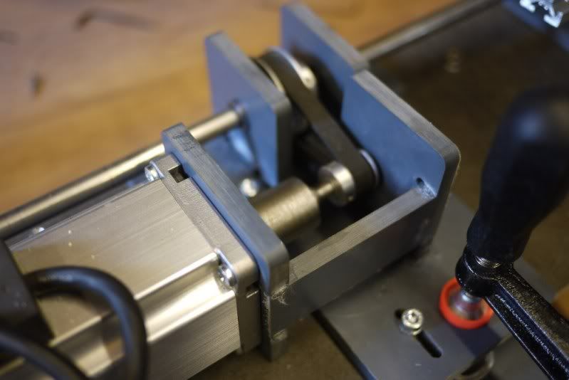
Thinking of possible ways to machine the ends of my ball screws. They are too hard to turn well in my Myford hobby style lathe, so I will need to aneal the ends of the screws or weld/glue a softer steel to the ends.
Here I have bored a 6mm hole in a piece of m12 threaded rod representing my ball screw. Then I turned down my steel rod at one end to slip inside the bore of the screw. This time I welded them together but I have heard some types of loctite will glue these part together just as well and this means I do not have to expose my screws to the heat of the welder.
As my welded in steel ends are about 18mm in diameter I will be removing plenty of material meaning the OD will become conentric to the rest of the ball screw.
Comment from: Enraged on Sunday, June 17th 2012 - 4:06 PM
they are usually hardened, so you need to grind off the top layer of metal. once you are through that, they cut very easily. it's also a great excuse for buying more tooling for your lathe
Sunday, June 17th 2012 - 4:19 PM
Do you use a bench grinder to grind of the hard part, or do you need some sort of specialized lathe mounted grinder?
The problem with this option is my bearings are 12mm and the screws are 15mm. At 12mm I may just be under the surface of the lower part of the screw threads making threading difficult. I could maybe change to 10mm support bearings but this would mean faffing around with mail order returns, but I would then be well under the hardend areas.
something like that would work, and I would imagine you could fab your own rather than buying one.
Friday, June 22nd 2012 - 10:21 AM
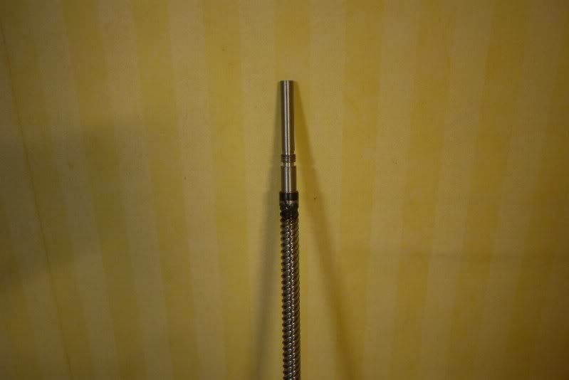
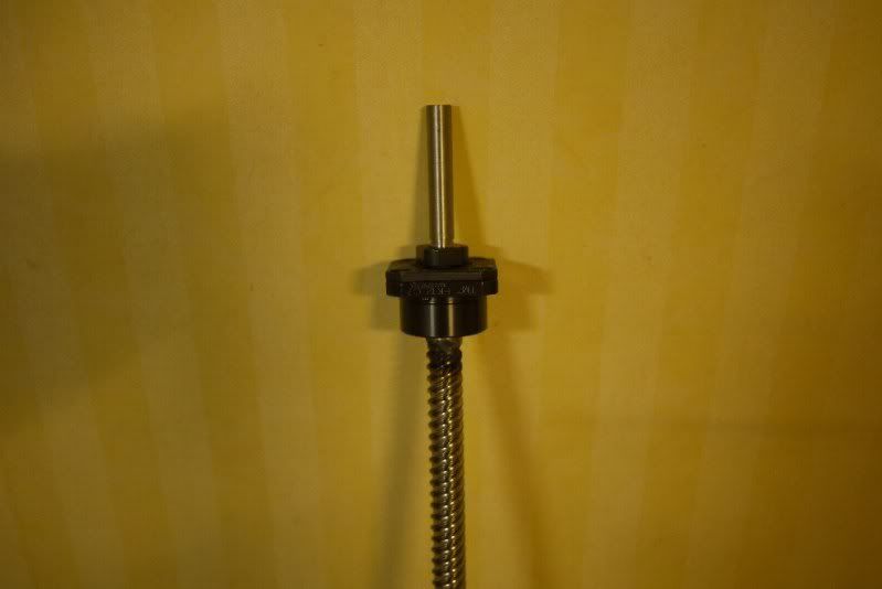
Ball Screws and bearings arrived today, one of the ball screws was bent quite a bit in multiple directions which was a bit disappointing but I think I can bend it back into shape. There are four "threads" running alongside each other, so in the photograph the screw appears to have quite a short lead. The lead of the screw is 20mm and the diameter 15mm.
Comment from: Liberty4Ever on Friday, June 22nd 2012 - 4:50 PM
That begs the question... how does someone bend a 15mm diameter ball screw? Did they use it as a pry bar to lift concrete beams to free victims trapped in earthquake wreckage before shipping it to you? I know kids with that special power. Give them an anvil for Christmas and they'll tear it up Christmas morning.
Bummer about your ball screw. Hopefully there is a replacement coming soon.
Comment from: macona on Saturday, June 23rd 2012 - 9:56 AM
Good luck straightening one. It is an art to straighten a ball screw to a point where it does not wobble when being used.
To machine them you just need a carbide insert. You can cut past the hard surface without too much of a problem. I had the do the 1-1/2" diameter one on the Z axis of my mill. Hardened steel is not too big of a deal as long as you have a solid machine. Also cermet inserts work even better.
Saturday, June 23rd 2012 - 11:19 AM
Good luck straightening one. It is an art to straighten a ball screw to a point where it does not wobble when being used.
Hopefully this will be a last resort, Im hoping my supplier will replace the screw free of charge. He has gone rather quiet after I sent photos of the screw.
To machine them you just need a carbide insert. You can cut past the hard surface without too much of a problem. I had the do the 1-1/2" diameter one on the Z axis of my mill. Hardened steel is not too big of a deal as long as you have a solid machine. Also cermet inserts work even better.
I only have a Myford hobby lathe which I assumed would not be up to the job of cutting through the case hardening. Would you advise against welding an easily machinable end onto the screw, apart from looking rather messy im hoping it will work fine?
Comment from: educa on Saturday, June 23rd 2012 - 12:16 PM
Bent ballscrew ? RETURN TO SENDER! You don't pay that amount of $$$ for a bent screw
Saturday, June 23rd 2012 - 2:43 PM
Picked up some 10mm aluminium tooling plate today. I intend to use this for various brackets and mounting surfaces on the redesign. Its very hard, unlike most alu I've seen before and it has a ring to it when struck. Hope it won't be too hard going for my router.
Comment from: SpacedCowboy on Friday, June 29th 2012 - 4:33 AM
Bit of an aside: what spindle-speed, depth-per-pass, ipm and drill do you use for routing out Al ? I'm going to have to do some soon, and I've never routed Al. Are you using any coolant or directed air blown / sucked to help out ?
Cheers, Simon.
Friday, June 29th 2012 - 8:24 AM
Simon, this was my first attempt, but these are the settings that worked best for me. I used mm/min
Plunge speed was kept at 40mm/min for all cuts. The router complained most when the plunge speed was much higher than 40.
Spindle speed was set as low as I could set it before I heard any strange noises. Wood routers like the little Bosch are not ideal as they generally spin way too fast for aluminium cutting.
Pass depth was 1mm.
End mill was a 5mm carbide up cutting bit.
No coolant or directed air.
Speed was 100mm/min for the holes then 300mm/min for profiled outside.
Comment from: SpacedCowboy on Friday, June 29th 2012 - 6:04 PM
Thanks Much appreciated
Simon
Wednesday, July 4th 2012 - 11:32 AM
Spaced Cowboy, I routed out a few more parts yesterday.
I had problems routing out the outer profiles at a speed of 300mm/min the alu melted and stuck to the bit causing the router to stall. Slowing down the router to 120mm/min for all cuts seem to work better. My spindle speed was about 17,000 Rpm.
I have a motor and a screw on each side of the gantry. If one motor decides to move and leave the other behind, it was cause damage to multiple parts of the laser.
I have an idea to create a safety system to de-power the servo drives if the gantry runs out of parallel. It would be based on an ardunino laser trip wire project of which there are many iterations online, here is one for example
Like the example above I would have the laser mounted one side of the gantry and an LDR connected to the other side.
When the gantry moves out of alignement the laser would move off target and sound the alarm, instead of a buzzer I would have a relay which would supply 12v to the servo enable pins.
Comment from: Liberty4Ever on Wednesday, July 4th 2012 - 1:31 PM
Using a laser to monitor a laser. Cool. That reminds me of a joke. Paraphrased: My laser has it's own laser, and even its laser is cooler than your laser.
I'd be tempted to replace that Arduino with an op amp comparator to set the trip level voltage from the photocell. Of course, I don't have an Arduino in my parts bin, but I have lots of inexpensive op amps. Use what you have. And as Steve Ciarcia would say on the issue of what to implement in hardware and what to implement in software... "I program in SOLDER."
My first inclination would generally be to avoid designs where two motors could be out of sync and rack the gantry at a harmful angle, but given the advantages of the dual motor design, this looks like a very appropriate solution to me. The Hadron printer I'm building uses two Z stepper motors driving a threaded rod on each end. Fortunately, I don't think those motors are powerful enough to damage the stouter Hadron mechanics because the Hadron is small and the motors don't have the leverage that you have on a long laser gantry.
Wednesday, July 4th 2012 - 9:17 PM
Glad you like it Liberty. I know very little about electronics so I thought an arduino would be the simplest way. There's plenty of documentation for various projects on the web, but I agree the simplest elegant solution is always the best but for some reason I want to include an Arduino with a lcd screen just for the heck of it.
Here are some aluminium parts fresh off the router. Each part takes about 1 hour 15 mins, and I need 10 separate pieces (2 of each). Because it's aluminium I need to baby sit it, which takes all the fun out of it, watching it slowly bite its way round the table quickly loses any appeal. On the plus side the parts look great and have plenty of strength in them to resist bending.
Comment from: Liberty4Ever on Wednesday, July 4th 2012 - 10:19 PM
gavztheouch wrote:Because it's aluminium I need to baby sit it, which takes all the fun out of it
Yeah, but those parts look great!
When I have a big laser job, I web surf (often BuildLog.net) while babysitting the laser. Yet another advantage to having internet access in the shop and Firefox on every PC based CNC machine tool.
I'm going to go work on my Hadron Ord Bot. I've been away from it for a week or so, and I'm eager to wrap it up.
Comment from: Liberty4Ever on Wednesday, July 4th 2012 - 10:46 PM
If you'd like to repurpose that Arduino (as the controller for a 3D printer!), here's an op amp based laser trip wire detector circuit that definitely SHOULD work. I didn't actually build it, but it's a simple circuit. The values aren't critical. They're just voltage dividers. You could use a 10K potentiometer, or a 47K, or 1K. Once you determine the correct ratio, you could substitute fixed resistors. If you need more current than the op amp can supply, you can add a transistor to the output to amplify the current. Swap the + and - inputs to the op amp and it's a laser detector instead of a laser absent detector.
Inexpensive op amp circuit to detect a low power laser beam. Could be used to determine if a malfunction has occurred and one of two motors has stopped, which would rack the gantry on a laser engraver and possibly damage the hardware.
Friday, July 6th 2012 - 7:36 PM
Cool thanks for the sketch, I will try and mock one up when my breadboard arrives. I made an Arduino based version last night and it works great, now I have the electrical part roughed out I will need to look into the mechanicals, I already have a rough idea of how its going to work but the devil may well be in the detail with this one.
I have managed some more progress with the ball screws brackets here is a picture of the motor and fixed end ball screw mount.
I am happy with how rigid these are and once they are bolted to the frame things can only get stiffer.
Good news and bad news today. The good, the ball screws and servo motors are working, the bad, I still have "backlash" style symptoms.
I am a little disappointed in the end result but It has been a great learning curve machining the ball screws and mounts and I feel it has been worth it converting from belts. The one glimmer of hope I have right now is the backlash style errors get worse at speed, between speeds of 1 moving up to 2 in the dsp the backlash more than doubles. Unlike the belts the screws cannot deform/stretch under speed so I would guess the errors are coming from the motor losing it position and not backlash in the screw? or possibly a bug in the DSP controller. Maybe I should switch back to mach 3 and test my vectors again.
Comment from: Liberty4Ever on Wednesday, July 18th 2012 - 3:08 AM
You have a light load and a relatively heavy ball screw, but the screws seem fairly long. Are you seeing screw windup with fast acceleration? Ball screws have a large pitch, so it wouldn't take much torsional deflection to result in some axial motion that would appear similar to dynamic backlash. The other possibility I can conceive would be flexing in relatively long and unsupported ball screws. Either of these problems should be dynamic problems, causing following error when in motion, but not a loss of accuracy when the axis has reached a destination and come to a stop, and any twisting or bending of the ball screw has been eliminated. Are you seeing following error based on observations of cut quality, or are you measuring positioning errors where the commanded motion doesn't match the actual motion after the axis has stopped moving?
One trick for eliminating screw windup is to put an encoder on each end of the ball screw to measure the windup (difference between the two encoders) and compute the axis position based on the screw windup evenly distributed across the length of the screw. The farther the ball nut is from the motor, the larger the windup error. But I doubt your controls are up to that sort of ball screw windup compensation.
Of course, in an open loop stepper motion system, losing steps is always a possibility. More or less microstepping could help, or slowing the motion (probably not what you want to do), or more motor current, or bigger stepper motors. Occasionally, faster motion will prevent lost steps if the steady state speed results in harmonics the stepper motor doesn't like, and the ramp up and ramp down isn't in the harmonic zone long enough for the amplitude to build to a level that causes missing steps.
Wednesday, July 18th 2012 - 5:19 PM
Thanks for your thoughs Liberty your help is appreciated. Today I switched from the DSP to Mach3 and surprise my vectors were much nicer. Visually you really need to look for the signs of any backlash. I now have a measured backlash value of 0.05mm in the Y which is great.
Here is a similer backlash snake to the one igull was using to diagnose his backlash problems in another thread. You can see all horizontal lines line up quite well. As I was using mach3 I can tweak my backlash comp, you can also use this to give your system artifical backlash. I gave it a value of 0.2mm in the Y. This made all the lines visually off by quite some bit. I gradually lowered the value of backlash comp, watching the lines start to realign themselves. Around 0.02-0.03 I could not see any backlash at all and removing the backlash comp gave what you see in the pic, perfectly decent vectors.
So now I need to figure out what is wrong with the DSP for it to make such a mess of the vectors, there is also a good chance there was also nothing wrong with my last belt setup.
Comment from: iGull on Wednesday, July 18th 2012 - 7:08 PM
Hi Gav
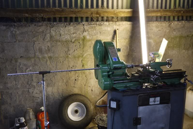
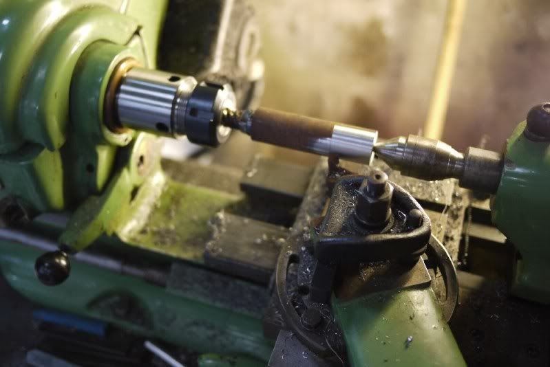
Just noticed your new setup - looking really good ! Loved the anti- whip support for the ballscrew end machining - looks like my old music stand 50um, I wish that was what I had
Regarding the snake data to show up backlash, I swapped to 'waves' of half arcs - the backlash showed up instantly - it's amazing how accurate your eyes are.
Anyway, regarding the dsp and 'backlash' (although this isnt realyl backlash). On my system, I had to set the Y axis steps/um different from the X (X was as calculated using the pitch circle diameter of the pulleys - bang on) - to date, I haven't found out why (I did actually swap drive pulleys and drives to see if that was a cause). Both axes now use exactly the same steppers and belts - the belts are even from the same reel. I did the settings over 500mm on both axes - checked the diagonals were equal too. I also measured multiple square test pieces. All dead nuts on, but the axis steps are different. I began to think like you ,that there was some issue in the pulses from the dsp. I no longer have access to any decent test equipment - a pulse counter would be a good thing to hang on the step outputs during a 45deg diagonal move with the same steps/um on each axis. I also tried a change in step polarity
I don't remember having this issue using the lasersaur board, but I had a lot of backlash at that time caused by those split couplers which may have masked it I no longer have the board, I mailed it to a friend for his laser. Hopefully, you'll get to the bottom of it using mach - look forwrd to yourr results. Cheers Neil
Comment from: Liberty4Ever on Wednesday, July 18th 2012 - 7:55 PM
So, are you saying that what you were observing and reporting as backlash may have been uncoordinated motion by the DSP controller?
Stuff like that is why I was recommending a static measurement of backlash rather than inferring backlash from print quality or some other indirect method. True backlash should be relatively easy to measure. If something can be measured directly, that is by far my preference. No point introducing complexity and uncertainty about what you're measuring or observing. That can lead to replacing belts with ball screws when the belts were actually OK.
Of course, hind sight is always 20/20.
My current CNC retrofit project uses LinuxCNC and I've been bumbling along on the edge of effectiveness for too long. I'm finally starting to see some progress. If I knew what I was doing when I started I could have saved at least 90% of the effort so far. That knowledge comes at a high price. Welcome to the bleeding edge of project build craziness. On the plus side, my next two (or more) LinuxCNC projects should be much easier, but you probably aren't planning on building another laser engraver.
Maybe I can learn from you and others on BuildLog.net, so my future laser build goes a bit more smoothly. It'll probably be a LinuxCNC project!
Comment from: iGull on Friday, July 20th 2012 - 3:31 PM
Liberty4Ever wrote:So, are you saying that what you were observing and reporting as backlash may have been uncoordinated motion by the DSP controller? Stuff like that is why I was recommending a static measurement of backlash rather than inferring backlash from print quality or some other indirect method. True backlash should be relatively easy to measure. If something can be measured directly, that is by far my preference. No point introducing complexity and uncertainty about what you're measuring or observing. That can lead to replacing belts with ball screws when the belts were actually OK.
This is a slim possibility, but I have no real way of proving it - unless I can get my hands on a pulse counter - I've attached a screendump of my system settings. I'm not entirely sure it's actually the case. I have also cut a 500mm L shape where the line is cut contiguously - effectively nulling any backlash as that would have been taken up in it's initial positioning (I purposely set the directions then nailed the datum) and there have been no reverse directional changes made - the lines were orthogonal and of equal length. Doing a quick calculation, over 500mm, the step count difference between the two axes is 22328 steps. At the X step size, that equates to just over 1.9mm - which seems quite a lot over 500mm. I did some further testing last night, and my machine cuts dead square and size accurate to within 0.05mm 'ish - over the 150mm my vernier works. Over 150 to 500, it's difficult to gauge accurately - flat ended steel rules aren't really that accurate (dimensionally), but are fine for consistency - my sizes are consistently the same in X & Y. Different materials give differing results of course as expected. I do see an amount of backlash on wee circles (3mm or less) - it's visible, hardly measureable accurately - but I now cheat and set those circles to be cut at a much slower rate which improves matters. I use an offset of 0.1mm which is fine for any work that I need an accurate fit on (mainly balsa/liteply/acrylic) - this is with a 63.5mm lens. To be honest, it can all get a bit anal can't it At the end of the day, I'm only cutting bits of wood and what I get from the system is perfectly OK. My real feeling is that this is all mechanical imperfection, but I'd like to just count the pulses to give me a nice psychological warm feeling anyway
I apologise if this is hijacking Gav's thread, I'm not intending to - I just don't want to see his ballscrews go to waste LOL It may all be a factor.
I'm not sure I understand what a 'static backlash' measurement is 'though ? By inference, 'backlash' has to include movement?
Cheers
Neil Attachements...
System settings
Comment from: jv4779 on Friday, July 20th 2012 - 9:28 PM
iGull wrote:I'm not sure I understand what a 'static backlash' measurement is 'though ? By inference, 'backlash' has to include movement?
http://www.cncexpo.com/MeasuringBacklash.aspx shows the procedure. In summary, move into a dial indicator, zero the indicator, then move off. The difference between what the computer thinks it moved and the reading on the dial is the backlash.
This is obviously easier to do on a cnc machine that has jog or mdi support.
Saturday, July 21st 2012 - 11:33 AM
I heard someone using the term dynamic backlash to included things like belt stretch and other variables related to the acceleration/de-acceleration of the gantry. So I assumed "static" backlash could be used to described just the mechanical backlash, ie only measuring backlash when the gantry is not moving, but there are multiple movements in-between. Not quite sure if that makes sence, I think I just confused myself.
Comment from: Greolt on Saturday, July 21st 2012 - 9:41 PM
Have you tried your test while setting Step Edge to "Falling"?
Greolt
Comment from: Liberty4Ever on Sunday, July 22nd 2012 - 4:49 AM
I made up the term "static backlash". There is probably a real static backlash, and my made up version is probably different from the real version.
It's true that backlash inherently requires motion, so in that sense, I don't see how there could be static (no motion) backlash.
What I meant by "static backlash" is real, mechanical backlash, the measurement of which was described in the post by jv4779 a couple of posts earlier in this thread... as opposed to what was being described as backlash but seemed to be inferred from laser cutting errors. Some forms of control errors or electrical problems could mimic backlash, and if they were assumed to be backlash when they weren't, a lot of time and money could be wasted trying to fix nonexistent backlash.
I plan on using LinuxCNC when I eventually build a laser, so I'll be able to enter MDI commands or manually jog the axes, so measuring backlash (and entering backlash compensation) should be very easy. Of course, engraving with LinuxCNC requires a multi-step image-to-Gcode conversion. I do a lot of engraving, but it tends to be the same engraving over and over again, as opposed to the custom work that a sign shop, trophy shop, or electrical machinery label maker would do where every job is different. The tedious but infrequent conversion for engraving won't bother me too much and I can just run the same G code each time I make new parts.
Wednesday, July 25th 2012 - 6:31 PM
Hi, today I made a video of myself testing the backlash in my y-axis.
The first few movements are 1mm, then I move on to increments of 0.1mm then 0.05mm and finally 0.01mm
For each different increment value I first make multiple movements in one direction then reverse the direction for a similer number of movements.
I reckon there is about 0.03mm backlash, what do you guys think.
Im using a 10mm travel dial test with 0.01mm increments on the dial
I may have found the answer to my "dynamic backlash issue", I think it is down to the servo motor tuning. I have them way to spongy.
I didn't relise this was possible but you can hook the panasonic servo drives up to a pc via a RS232 cable while the dsp is running and plot a grapth of the postion error on the screen. It shows the motors losing postion at the change of direction, I think this is due to the motor not being tuned so they are stiff enough to resist the momentum of the gantry.
Comment from: Techgraphix on Wednesday, July 25th 2012 - 8:58 PM
So all the ballscrew-effort wasn't neccesary at all????
Kees
Wednesday, July 25th 2012 - 10:38 PM
Quite possibly ... Still I learn't a hell of a lot from the install and I think il have a decent machine by the end of it if I iron out the remaining problems.
After tweaking, postional error in the servo motor is now down to 20 pulses when engraving using the y-axis. This is from a starting error of 160 pulses before tweaking.
With 5000 pulses per rev and a pitch of 20mm thats 0.004mm per pulse, making 20 pulses 0.08mm
Starting to make some progress and hopefully the servos can be tuned better than it is now.
The next job is to staighten the ballscrews as at least one has been bent out of shape quite badly. After that I need to look at improving the x-axis. Currently im using a mxl pitch belt over about 1.4m of total travel. I reckon this would benifit from a wider and larger pitched belt. Mabey 3mm HTD 15mm wide.


 add comment in the forum
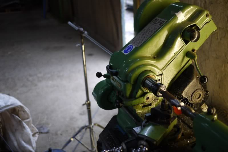
Hi Gav
Worrying, that's a similar type of belt I'm using (from motionco - HTD 9mm wide 3mm pitch , aluminium pulleys). After replacing my slotted shaft couplers for the same ones you are using (marchantdice), my backlash virtually disappeared. I say disappeared in the loosest sense, there is obviously still some, but it's barely visible (it's measurable of course- approx 0.1/0.2mm 'ish). To be honest, visible is more important to me than measurable these days as I no longer build parts for the hubble
I'll follow this new thread with interest, are you considering trying HTD in a different type of material? If so, then I'd be interested in any improved results (so I can change mine if it works, or let you spend the money if it doesn't
Ballscrews should prove interesting, high helix screws are certainly not cheap, and in the size you need, they'll need to be rigid - you won't get away with little teflon coated jobs at 6mm diameter and 20mm pitch
Good luck with the mk2, it's looking good. I do fancy another build, slightly smaller perhaps (700-900mm X) and with decent quality slides like yours. I have a huge THK linear slide sitting in the garage, but it's just too hefty for a laser - more suited to that heavy duty cnc router.
Cheers
Neil