Buildlog Title: Terje's buildlog


Builder: terjeio
Member Since: 2014-10-27
Thursday, November 20th 2014 - 5:22 PM
Hi all,
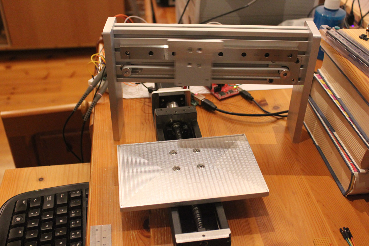
I have started building two lasers, one based on the 2.x design and a smaller one for exposing photosenstive PCBs by utilizing a 405nm laser diode.
The 2.x frame is nearly complete, waiting for bits & pieces from China so I can proceed with construction.
So, for now I am working on the PCB exposer, this is based on a TI MSP430 controller, FTDI USB -> UART communication and Polulu drivers.
Toolchain is Visual Studio 2010 and C# for converting a 1200 dpi BMP file to a datastream for the controller which code is implemented
by using CCS and C as the programming language. So far so good, axes are now moving and a more or less harmless red laser diode is happily blinking.
I have got the 405nm diode already but I am not ready to fire that up yet - I guess it is best to wait until the safety goggles arrives.
The plan for this is to implement a printer driver that can drive the exposer directly, maybe a bit ambitious - we'll see what I am able to put together.
The fun thing about the exposer controller is that it may be used for the 2.x as well, my initial plan was to control it from Mach3 but a combo might be a better idea?
I want PPI control and I am thinking of implementing the counters for this, and selection logic for swiching controllers, in a TTL-tolerant CPLD, again hopefylly within my abilities.
Prototyping for the PCB exposer:
Terje
 add comment in the forum
Thursday, December 25th 2014 - 4:58 PM
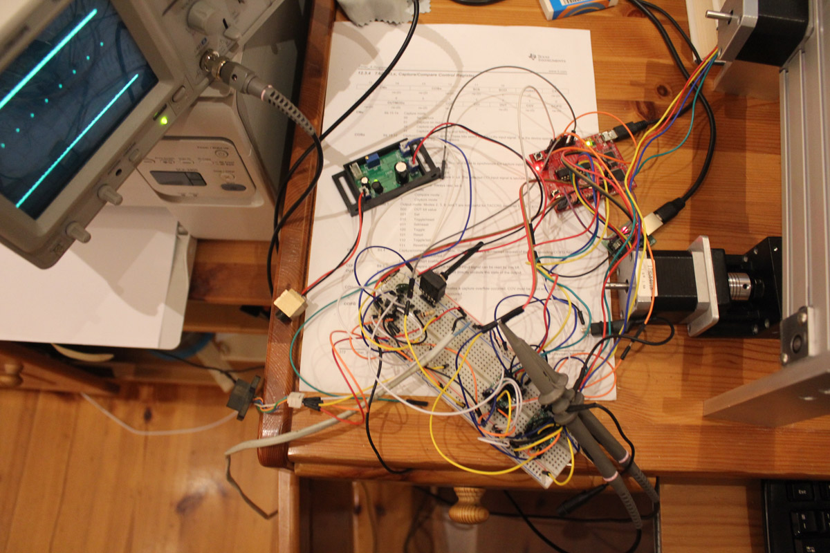
PCB exposer: after being forced to design my own diode driver due to the Chinese driver being totally useless I am now ready to move the electronics from a breadboard to some real PCBs. Hopefully I will then be able to get rid of some artefacts which I suspect is due to noise in the current setup...
Attachements...
 Viewed 55598 times")
- Detail of first succesful exposure, looks promising.
add comment in the forum
Friday, December 26th 2014 - 2:13 PM
PCB Exposer: problem solved, artefacts were a combination of buggy program, bad focus, laser power and noise. I am using Dupont dry film photoresist,
it is very sensitive and I have to run the diode just above its lasing threshold in order to avoid fogging around the tracks.
Attachements...
 Viewed 55563 times")
- SOT23 footprint, 0.5 & 0.3mm track widths - from final driver board
add comment in the forum
Friday, March 27th 2015 - 8:23 PM
After my 24V PSU literally blew up, I have been a bit slow on starting my 2.x build again. Luckily my drivers survived even as the PSU voltage surged to nearly 60V...
Yesterday I finally powered up the laser tube so I am now ready to move on. Today I have modified my PCB Exposer software to match the CO2 tube and the initial results looks promising.
Having been spoiled by the resolution of the 405nm laser it is quite a change to work with the CO2, I have started out with 3ms/pixel which seems to be a bit on the fast side. Maybe my tube/laser PSU combo is a bit slow to react, when I increase power to get single pixels to show up continuous pixels (> 10) gets too much power. Maybe this can be solved by implementing PPI?
Anyway, I think I'll stick to my plan to use my own software for engraving and Mach 3 for cutting for now.
Attachements...
 Viewed 54608 times")
- From my initital attemps at engraving, image is 90mmx90mm @ 300dpi on some scrap cardboard. Artefacts are from me moving the cardboard while engraving.
add comment in the forum
Wednesday, April 8th 2015 - 3:32 PM
My prototype controller is now working as it should so I have spent a few days designing a PCB for it. It will piggy-back onto a chinese breakout board to factilitate a clean interface to Mach 3. I have to submit it to fabrication as I am not able to make it myself, too many vias for that - I will not try plating it myself. The whole design is broken down into separate subsystems and I am using i2c for communation. The setup consists of no less than five MSP430 microcontrollers and two CPLDs... MSP430 are only a few euros each so cost is no issue. The separate processors are tasked with power control, input switch handling, relay control (fans, pump & air assist) & cooolant flow monitoring, PPI handling for Mach 3 and motor/laser control for bitmap rendering. The CPLDs are for the stepper pulse counters used for PPI, 24-bit each with latching since the counters are read a byte at a time. Laser power is controlled by a 12-bit DAC, maybe this will come in handy if I want to try grayscale engraving?
Attachements...
 Viewed 54427 times")
- Closed loop cooling, air intake is only ø 50mm - enough?
 Viewed 54427 times")
- Brushed aluminium skin, PCBs for power control & switches behind panels. I am abit old fashioned so no LCD-display, 7-segment leds for power level
 Viewed 54427 times")
- Coolant reservoir in electronics bay - maybe a bit dangerous?
 Viewed 54427 times")
- Closed electronics bay, air intake inside - hopefully it will work...
 Viewed 54427 times")
- Second mirror mount
add comment in the forum
Sunday, April 19th 2015 - 12:39 PM
Thanks for nice comments, it helps tremendously to have access to the wealth of information provided by all the previous builders.
My CNC mill is also a vital tool to have when fabricating parts.
I got my prototype controller PCB back from China a few days back, and I have now ported over my test program and the core functions are all up and running.
Next step will be to let Mach 3 gain control of the machine and then implement PPI control for cutting.
I will then try to implement a plugin for Mach3 - for controlling PPI, power and maybe even share current position with my controller...
Attachements...
 Viewed 49464 times")
- Two MSP430s on board, then main controller and a dedicated PPI processor. The second (now missing) CPLD will be added when I get the first working correctly.
 Viewed 49464 times")
- My controller on top of Mach3 breakout board.
add comment in the forum
Sunday, May 3rd 2015 - 3:36 PM
Finally got Mach3 working, some problems with the BOB as my CPLD-counters were counting more or less randomly when fed with pulses from Mach3. A pair of Schmitt-triggers cured that problem. PPI-control is a must, it gives very fine control of both engraving and cuts - however I need to add preset support to my control software as there are to many combinations to keep track of... I have used dirktheengs code as a starting point for Mach3 PPI-control but had to convert it to integer math as MSP430 is too slow to handle floating point in real time - I think any rounding errors due to this does not affect the final result that much. So, I have a useable machine now

Attachements...
 Viewed 49342 times")
- Engraving on paper, not possible without PPI?
add comment in the forum
Tuesday, June 21st 2016 - 1:33 PM
New controller made, have gone 32-bit - can now do a lot more fancy coding...
 Viewed 48315 times")
- New board
 Viewed 48315 times")
- Piggy back on Chinese breakout board (for Mach 3)
 Viewed 48315 times")
- (Nearly) same connections as Chinese breakout
 Viewed 48315 times")
- OLED display in front panel
Hardware:1. Main board3-axis motion controller for four motors, Y-output is switchable between two motors (Y or A)
Texas Instruments (TI) Tiva TM4C123GH6PM as main processor - ARM Cortex M4F: 80 MHz, 256 KB flash, 32 KB SRAM, 2KB EEPROM, ROM-based library (TivaWare)
TI MSP430G2553 MCU with two CPLDs provides PPI-control for lasers, controlled by main processor via I2C.
Isolated input via USB-to-serial (FT232RL) or direct serial provided by ADUM1402, optionally USB directly (not isolated).
I2C bus made available for add-on boards.
On board regulator for +5V, 6.5 - 36 V supply range (TRACO TSR 1-2450)
2. Relay control boardvia I2C - for air assist, coolant pump and fans, 4 channel board made.
3. Front panel boardsControl via I2C, for display and buttons. Board made with OLED display for status, 13 buttons for power, relay control, laser test fire and axis jogging.
Firmware/software:
Proprietary code for engraving, supporting desktop application written in C# for Windows.
Mach3 option via piggyback to common paralell port breakout board, supported in proprietary code (mode select).
PPI mode available, controlled by desktop application.
GRBL option in the making, code has been ported from latest version - must be integrated with proprietary code.
My plan is to make a HAL (Hardware Abstraction Layer) for GRBL, and change it into a library.
add comment in the forum
Monday, July 4th 2016 - 7:11 AM
Ready to try grayscale (3D) engraving - 128 levels implemented.

 Viewed 48041 times")
- Updated UI for grayscale engraving
add comment in the forum
Wednesday, July 6th 2016 - 9:13 AM
First attempt at grayscale/3D engraving were successful in that the software and hardware works as expected, only some minor software issues to be corrected.
However, I now face the problem of laser supply/laser tube linearity - the combo is not linear, that is the control voltage/laser output power has a nonlinear relationship.
My controller has a 12 bit DAC for adjusting laser power, which translates to 4096 discrete levels, however about half is lost due to the fact that the usable range is about 1.0 - 2.5V from a possible output of 0 - 3.3V. The output could be corrected for by adding an op-amp to set gain/offset, however I have opted for a software solution for now.
The software solution is based on a lookup table mapping percentage power (combined with an offset) to set control voltage. This has the bonus of beeing able to use a table that corrects for any linearity issues. Since I do not own a power meter I have run into the problem of creating such a table, I can of course try to create one by trial and error - but maybe someone else has created one that could be used as a starting point?
Since the controller has 2Kb of EEPROM I have implemented functionality to download a profile from the desktop application - no need to recompile new firmware.
 Viewed 47981 times")
- From the very first attempt at 3D engraving
add comment in the forum
Thursday, July 7th 2016 - 12:32 PM
Some progress, and got a crazy(?) idea about measuring (relative) power output for calibration - maybe a micrometer clock can be used? Plot a 3D grayscale in acrylic and measure depth of each level...
 Viewed 47953 times")
- 3D engraving in acrylic - laying flat...
 Viewed 47953 times")
- ... and held against light from the gray sky here today, Einstein is engraved @150dpi, cat @300dpi. 300dpi is minimum I think, at 150dpi each line is clearly visible.
add comment in the forum
Sunday, May 21st 2017 - 6:24 PM
I finally got around to integrate Grbl (v1.1) into my controller code, I have HALified Grbl in my port and made it into a library to achieve that. The driver layer supports custom M-codes for controlling the PPI-mode parameters, integration with front panel buttons (including jogging) and display. My desktop application has gained a gcode streamer tab supporting the Grbl streaming protocol and has support for 3-key rollover jogging via the PC keyboard. Some fine tuning remains for the UI, I need to use it a bit to find out what features to add...
 Viewed 44721 times")
- Grbl (gcode) tab in action
add comment in the forum
Wednesday, September 27th 2017 - 12:39 AM
As a coding excercise I have made a PSoC5 PPI module - a USD 10 CY8CKIT-059 development board is all that is needed, no external electronics. Step counters are implemented using PSoC UDBs - which are similar to FPGAs. Note that I am not going to use this design myself since my controller has PPI handling implemented using CPLDs.
The solution is available from my
Github account.
Terje
add comment in the forum