Quantum ORD Alternative
20 posts
• Page 1 of 2 • 1, 2
Quantum ORD Alternative
![]() by Pazu » Thu Apr 26, 2012 2:23 am
by Pazu » Thu Apr 26, 2012 2:23 am
Here's my build log for the Quantum. ORD Alt., "odd odd"... Geddit? Hehee.... OK lame.
Right when I first knew the build volume of the ORD bot, I knew I'd have to mod it. While Bart designed it to be very extensible, the foot print is something that I can't quite stand. Take for example the Quantum's width is more than twice the build volume width. For the X-axis which is a gantry, my feel is that it should be more economical in terms of space comsumption.
My target build volume is 150mm (x) by 210mm (y) by 120mm (z). Y axis is of course, easily extensible. Z is already within the original build volume.
My idea is to rotate the vertical Makerslides so that I can reduce the overall size of the bot while giving more space for the build platform.
Another thing I couldn't stand is the way the X motor is mounted. Somehow the spacers don't seem very rigid. The motor bracket looks much better.
Anyway, here's my build currently.


I have to say that I believe I didn't come up with a better design. Just one that saves more space. I'm certainly ending up having more parts.
Next up, I have to make a new gantry plate too.
Right when I first knew the build volume of the ORD bot, I knew I'd have to mod it. While Bart designed it to be very extensible, the foot print is something that I can't quite stand. Take for example the Quantum's width is more than twice the build volume width. For the X-axis which is a gantry, my feel is that it should be more economical in terms of space comsumption.
My target build volume is 150mm (x) by 210mm (y) by 120mm (z). Y axis is of course, easily extensible. Z is already within the original build volume.
My idea is to rotate the vertical Makerslides so that I can reduce the overall size of the bot while giving more space for the build platform.
Another thing I couldn't stand is the way the X motor is mounted. Somehow the spacers don't seem very rigid. The motor bracket looks much better.
Anyway, here's my build currently.
I have to say that I believe I didn't come up with a better design. Just one that saves more space. I'm certainly ending up having more parts.
Next up, I have to make a new gantry plate too.
- Pazu
- Posts: 24
- Joined: Fri Jun 17, 2011 3:35 pm
Re: Quantum ORD Alternative
![]() by orcinus » Thu Apr 26, 2012 3:07 am
by orcinus » Thu Apr 26, 2012 3:07 am
How's a single bolt more rigid than 4 spacers (w/ 4 bolts)?
I must admit the spacers looked a bit weak to me too in the photos and drawings, but holding the assembly in hand, i really don't believe they are anymore. Vibration could be a problem for them, as would substantial tangential force, but this is a 3D printer, not a router. I might be completely off, though, as usual
PS: I dig the more compact look! Looks much neater.
PPS: Won't your arrangement strain the front and top Z-axis v-wheels too much? With enough weight, it's basically going to be like your gantry is hanging on 2x two wheels instead of 2x three. Plus, i imagine that might introduce some backlash in Z.
- orcinus
- Posts: 720
- Joined: Tue Feb 14, 2012 4:03 am
Re: Quantum ORD Alternative
![]() by naPS » Thu Apr 26, 2012 3:21 am
by naPS » Thu Apr 26, 2012 3:21 am
orcinus wrote:PPS: Won't your arrangement strain the front and top Z-axis v-wheels too much? With enough weight, it's basically going to be like your gantry is hanging on 2x two wheels instead of 2x three. Plus, i imagine that might introduce some backlash in Z.
Yeah, it seems like it takes the portion of the machine that's moving the most and spaces it several inches off the supporting sections center of gravity. I would imagine it's going to put quite a load on the top wheels of the Z axis gantries. It's also going to make the spacers required to hold the threaded Z nuts fairly long, as they are going to have to meet with the center of the stepper motor, where as in the original design they are less than 1/2" thick. You would think that could introduce quite a bit of flex.
Interesting idea though, for sure. If you're in need of saving space, this could help.
- naPS
- Posts: 202
- Joined: Sat Apr 09, 2011 1:53 am
Re: Quantum ORD Alternative
![]() by Pazu » Thu Apr 26, 2012 3:34 am
by Pazu » Thu Apr 26, 2012 3:34 am
orcinus wrote:How's a single bolt more rigid than 4 spacers (w/ 4 bolts)?
Ah but now it's 4 bolts for the motor plus 1.
I have concerns about throwing the weight forward too. But IMO, it's not putting any much more weight on the Z axis than the original. The Z nut blocks will still be mounted directly on the original plate, just shifted in position.
Like I said, not a better design. Just one that saves space.
- Pazu
- Posts: 24
- Joined: Fri Jun 17, 2011 3:35 pm
Re: Quantum ORD Alternative
![]() by naPS » Thu Apr 26, 2012 4:29 am
by naPS » Thu Apr 26, 2012 4:29 am
Pazu wrote:I have concerns about throwing the weight forward too. But IMO, it's not putting any much more weight on the Z axis than the original. The Z nut blocks will still be mounted directly on the original plate, just shifted in position.
Right, it's not more weight, but it's the location of the weight. Think about a fat kid standing right at the end of the diving board where it's attached at the concrete. Now, think of that same fat kid standing on the end of the diving board that hangs out over the water. There's a significant difference in how the load is distributed, and quite a bit more force placed on the joint.
- naPS
- Posts: 202
- Joined: Sat Apr 09, 2011 1:53 am
Re: Quantum ORD Alternative
![]() by Pazu » Thu Apr 26, 2012 4:41 am
by Pazu » Thu Apr 26, 2012 4:41 am
I agree. It's definitely more weight for the z axis.
But the pivot isn't that much more forward and z axis doesn't really move much. Guess I'll find out when it's all done.
But the pivot isn't that much more forward and z axis doesn't really move much. Guess I'll find out when it's all done.
- Pazu
- Posts: 24
- Joined: Fri Jun 17, 2011 3:35 pm
Re: Quantum ORD Alternative
![]() by naPS » Thu Apr 26, 2012 5:12 am
by naPS » Thu Apr 26, 2012 5:12 am
Pazu wrote:I agree. It's definitely more weight for the z axis.
But the pivot isn't that much more forward and z axis doesn't really move much. Guess I'll find out when it's all done.
I hope it works good, it's innovative, and definitely a space saver.
- naPS
- Posts: 202
- Joined: Sat Apr 09, 2011 1:53 am
Re: Quantum ORD Alternative
![]() by orcinus » Thu Apr 26, 2012 11:47 am
by orcinus » Thu Apr 26, 2012 11:47 am
Is there any way you can flip the plates around, mount the two v-wheels on the front and one v-wheel on the back? That would at least distribute the load on the wheels more evenly.
- orcinus
- Posts: 720
- Joined: Tue Feb 14, 2012 4:03 am
Re: Quantum ORD Alternative
![]() by Pazu » Sun May 06, 2012 8:50 am
by Pazu » Sun May 06, 2012 8:50 am
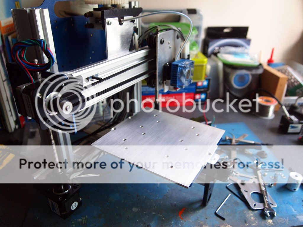
Took a bit of a break from the build because the changed configuration requires additional L-brackets.
Here's how it's like now. I build it up very roughly to gauge the feasibility. Seems like it will work out.


Next up is the extruder mount and I'll have to cut up the handle/electronics mount too.
Here's how it's like now. I build it up very roughly to gauge the feasibility. Seems like it will work out.
Next up is the extruder mount and I'll have to cut up the handle/electronics mount too.
- Pazu
- Posts: 24
- Joined: Fri Jun 17, 2011 3:35 pm
Re: Quantum ORD Alternative
![]() by Pazu » Tue Jun 05, 2012 12:57 am
by Pazu » Tue Jun 05, 2012 12:57 am
Some progress. Slow as I had to fabricate some parts.
I don't have any electrical tools that can cut the part so I use mostly hand tools. Fret saw in this case.
Marking with printed templates.

Sawing.
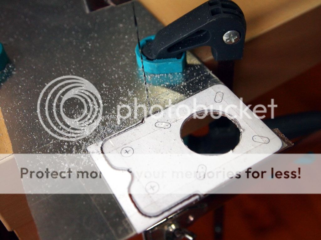
Done.


Here's how it currently looks like. Initial fears about the poorer weight distribution was unfounded. The thing is as solid as a rock.
I don't have any electrical tools that can cut the part so I use mostly hand tools. Fret saw in this case.
Marking with printed templates.
Sawing.
Done.
Here's how it currently looks like. Initial fears about the poorer weight distribution was unfounded. The thing is as solid as a rock.
- Pazu
- Posts: 24
- Joined: Fri Jun 17, 2011 3:35 pm
20 posts
• Page 1 of 2 • 1, 2
Who is online
Users browsing this forum: No registered users and 7 guests