Laser interface driver + DSP
Moderator: twehr
10 posts
• Page 1 of 1
Laser interface driver + DSP
![]() by J45on » Sat Jul 16, 2011 9:37 pm
by J45on » Sat Jul 16, 2011 9:37 pm
I have a DSP on it's way and I am a little confused about how to wire it up to Bart's Laser Interface/Driver 
I have ordered the 25pin connector and hood to make a cable.
I only want to use the Laser Interface/Driver for it's stepper drivers only,all other controls and limits etc will go to the DSP.
This snap sort of makes sense to me but do I need the 5v wire as the Laser Interface/Driver already has 5v ?
But this one just confuses me it is from this post viewtopic.php?f=32&t=661&p=4883#p4883
do I need the enable pin (16) connected to anything ?
Sorry if these are daft questions
I really should have bought separate drivers but I did not bank on being able to afford a DSP straight away and was planning to use mach3 .
What I could really do with is a "wiring bart's Laser Interface/Driver to a DSP for dummies diagram"
- J45on
- Posts: 258
- Joined: Thu Mar 31, 2011 11:30 am
- Location: Kent,united kingdom
Re: Laser interface driver + DSP
![]() by naPS » Sat Jul 16, 2011 10:30 pm
by naPS » Sat Jul 16, 2011 10:30 pm
I'm fairly certain that the DSP takes the place of the Interface board.
- naPS
- Posts: 202
- Joined: Sat Apr 09, 2011 1:53 am
Re: Laser interface driver + DSP
![]() by bdring » Sat Jul 16, 2011 11:32 pm
by bdring » Sat Jul 16, 2011 11:32 pm
The laser interface/driver PCB has a lot of circuitry that won't be used with the DSP controller, but the stepper drivers can still be used. I am guessing, but I would try this.
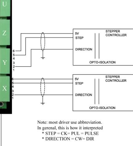
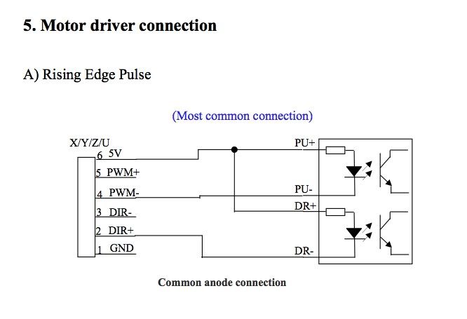
The schematics show the controller hooked up to opto isolated drivers. Optos invert the signals so that is why everything looks a little backwards. I would suggest hooking the DSP ground pin to any pin 18-25 on the interface board. I would then hook PWM+ to a step pin (2,4 & 6) and the DIR+ to the corresponding Dir pin (3,5 & 7). It looks like the pin out table wrapped the last row that shows (18-25 as ground) to the next page.
The schematics show the controller hooked up to opto isolated drivers. Optos invert the signals so that is why everything looks a little backwards. I would suggest hooking the DSP ground pin to any pin 18-25 on the interface board. I would then hook PWM+ to a step pin (2,4 & 6) and the DIR+ to the corresponding Dir pin (3,5 & 7). It looks like the pin out table wrapped the last row that shows (18-25 as ground) to the next page.
Bart
"If you didn't build it, you will never own it."
"If you didn't build it, you will never own it."
- bdring
- Site Admin
- Posts: 2966
- Joined: Sun Nov 22, 2009 7:33 pm
- Location: Chicago, IL, USA
Special DSP version of the interface/driver PCB
![]() by bdring » Sun Jul 17, 2011 1:31 pm
by bdring » Sun Jul 17, 2011 1:31 pm
If anybody wants a simplied version of the interface/driver for use with a DSP controller, I can do that. It would probably knock half the cost out. I would just populate only the needed items.
Bart
"If you didn't build it, you will never own it."
"If you didn't build it, you will never own it."
- bdring
- Site Admin
- Posts: 2966
- Joined: Sun Nov 22, 2009 7:33 pm
- Location: Chicago, IL, USA
Re: Laser interface driver + DSP
![]() by metalman » Sun Jul 17, 2011 2:42 pm
by metalman » Sun Jul 17, 2011 2:42 pm
For folks like me trying to decide which route to take, it would be helpful to have a comparison breakdown of the hardware and software needed for each way of doing the motion control. Of course along with the costs of each component, the special features, learning curve, setup time, performance, and other pros and cons would be helpful. With all the variables its a challenge to see what's the best bang for the buck.
- metalman
- Posts: 33
- Joined: Tue Aug 31, 2010 3:03 am
Re: Laser interface driver + DSP
![]() by J45on » Sun Jul 17, 2011 4:31 pm
by J45on » Sun Jul 17, 2011 4:31 pm
naPS wrote:I'm fairly certain that the DSP takes the place of the Interface board.
the DSP will still require stepper drivers that is what I am hoping to use the interface board as
bdring wrote:The laser interface/driver PCB has a lot of circuitry that won't be used with the DSP controller, but the stepper drivers can still be used. I am guessing, but I would try this.
The schematics show the controller hooked up to opto isolated drivers. Optos invert the signals so that is why everything looks a little backwards. I would suggest hooking the DSP ground pin to any pin 18-25 on the interface board. I would then hook PWM+ to a step pin (2,4 & 6) and the DIR+ to the corresponding Dir pin (3,5 & 7). It looks like the pin out table wrapped the last row that shows (18-25 as ground) to the next page.
Thanks bart
I will give that a try when my parts turn up.
bdring wrote:If anybody wants a simplied version of the interface/driver for use with a DSP controller, I can do that. It would probably knock half the cost out. I would just populate only the needed items.
Sounds interesting how would it compare to just buying stand alone stepper drivers ? would it be a new board ?
- J45on
- Posts: 258
- Joined: Thu Mar 31, 2011 11:30 am
- Location: Kent,united kingdom
Re: Laser interface driver + DSP
![]() by naPS » Wed Aug 03, 2011 5:55 pm
by naPS » Wed Aug 03, 2011 5:55 pm
So I totally get what the original post is about now. I was confused with my earlier post.
I'm also looking at either the RetinaEngrave or the DSP. The advantage of the RE is that I can use my existing electronics, which is the Pololu interface, and not have to change anything when switching from Mach3 to the RE software. I tested this last night, and it worked great. I enjoy using Mach3, because I can use Cut2d and correct for beam width and where I want it to actually cut (on line, inside line, outside line, etc.) really easily. The commercial controllers all require me to do that work in another piece of software, which is painful to me. So for purely vector work, Mach3 is the way to go for me.
However, it sucks for combined raster & vector work, which is something the commercial controllers excel at.
I think getting the DSP to utilize the interface drivers via the parallel port is a fairly simple exercise. The trick comes in with getting some of the stuff already built into the laser to translate over via the parallel port as well. I'm just knowledgeable enough to be dangerous with most electronics stuff, so here's my list of things that would need to be addressed to assemble a DSP -> parallel cable that could be unplugged if someone wanted to switch back to Mach3 control :
1. Stepper motor connections
2. Motor enable / disable doesn't seem to be a function on the DSP. This pin would have to be sent a signal from something.
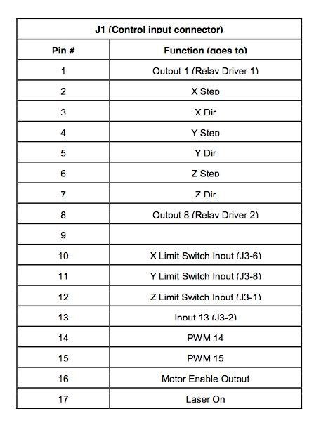
3. X / Y axis limit switches - there's a signal pin on the parallel port, but it appears to be inverse from what the DSP is looking for according to Tims writeup. Although, a cursory scan of the DSP manual looks like this parameter is possibly adjustable? It's looking for a a ground signal when the limit switches are hit, and an open signal when they are not active. This is opposite of how the laser is currently wired. Could the wire on the switches be moved to the other terminal (NO vs NC) and the Active High / Low changed in Mach3? If this is possible, it seems like an easy way to address this. If this is the case, then could we just use the X / Y limit switch pins (10 and 11 on the parallel port) as inputs to the DSP's X / Y limits.
4. Laser control seems pretty straight forward. We can send the "Laser Intensity" signal from the DSP into pin 14 or 15 of the parallel port. The TTL-High output would then go to pin 17 on the parallel port. Ground could go from any pin 18-25. I'm assuming that "Water protection" would have to be jumpered out on the DSP. An alternative would be to use Pin 13, which is the input from J3-2, and connect that to some sort of flow sensing device. However, I expect that 99% of the users out there currently have their water switch jumpered out.
Looking at the schematic, it looks like sending the Laser Intensity through pin 14/15 and having the switch set to "PWM" should bypass the pot entirely.
If the output for the X/Y Limit can't be reversed, I think this would be fairly simply rectified using a small pcb with a couple of opto's or something similar, would it not?
I'm also looking at either the RetinaEngrave or the DSP. The advantage of the RE is that I can use my existing electronics, which is the Pololu interface, and not have to change anything when switching from Mach3 to the RE software. I tested this last night, and it worked great. I enjoy using Mach3, because I can use Cut2d and correct for beam width and where I want it to actually cut (on line, inside line, outside line, etc.) really easily. The commercial controllers all require me to do that work in another piece of software, which is painful to me. So for purely vector work, Mach3 is the way to go for me.
However, it sucks for combined raster & vector work, which is something the commercial controllers excel at.
I think getting the DSP to utilize the interface drivers via the parallel port is a fairly simple exercise. The trick comes in with getting some of the stuff already built into the laser to translate over via the parallel port as well. I'm just knowledgeable enough to be dangerous with most electronics stuff, so here's my list of things that would need to be addressed to assemble a DSP -> parallel cable that could be unplugged if someone wanted to switch back to Mach3 control :
1. Stepper motor connections
2. Motor enable / disable doesn't seem to be a function on the DSP. This pin would have to be sent a signal from something.
3. X / Y axis limit switches - there's a signal pin on the parallel port, but it appears to be inverse from what the DSP is looking for according to Tims writeup. Although, a cursory scan of the DSP manual looks like this parameter is possibly adjustable? It's looking for a a ground signal when the limit switches are hit, and an open signal when they are not active. This is opposite of how the laser is currently wired. Could the wire on the switches be moved to the other terminal (NO vs NC) and the Active High / Low changed in Mach3? If this is possible, it seems like an easy way to address this. If this is the case, then could we just use the X / Y limit switch pins (10 and 11 on the parallel port) as inputs to the DSP's X / Y limits.
4. Laser control seems pretty straight forward. We can send the "Laser Intensity" signal from the DSP into pin 14 or 15 of the parallel port. The TTL-High output would then go to pin 17 on the parallel port. Ground could go from any pin 18-25. I'm assuming that "Water protection" would have to be jumpered out on the DSP. An alternative would be to use Pin 13, which is the input from J3-2, and connect that to some sort of flow sensing device. However, I expect that 99% of the users out there currently have their water switch jumpered out.
Looking at the schematic, it looks like sending the Laser Intensity through pin 14/15 and having the switch set to "PWM" should bypass the pot entirely.
If the output for the X/Y Limit can't be reversed, I think this would be fairly simply rectified using a small pcb with a couple of opto's or something similar, would it not?
- naPS
- Posts: 202
- Joined: Sat Apr 09, 2011 1:53 am
Re: Laser interface driver + DSP
![]() by bdring » Wed Aug 03, 2011 8:29 pm
by bdring » Wed Aug 03, 2011 8:29 pm
2. I would place the jumper in the 'D' position and run pin 16 to ground through a switch for the enable/disable.
3. I would just move the limit switch terminals to make the switch open during normal operation. You can run the 'D' connector limit switch wires to the DSP or you can bypass my board entirely on the limits switches and go straight to the DSP.
4. There are probably a few ways to do this. Again, you could skip my board entirely for the laser control.
Bart
"If you didn't build it, you will never own it."
"If you didn't build it, you will never own it."
- bdring
- Site Admin
- Posts: 2966
- Joined: Sun Nov 22, 2009 7:33 pm
- Location: Chicago, IL, USA
Re: Laser interface driver + DSP
![]() by naPS » Wed Aug 03, 2011 9:52 pm
by naPS » Wed Aug 03, 2011 9:52 pm
For 2, I believe I can just put the jumper in the 'D' position like you suggest, and then change the motor enable to Active Low in Mach3. That would take care of that I guess.
Or, there's an output on the DSP that I would imagine could be configured to do this, but I'm starting to think that just a manual switch connected to the parallel cable would be the best way to go about it. I guess it just depends on what the 5v output on the "IO" terminal block actually does, and how it's controlled.
I really would like to avoid having multiple connections to things, and would like to be able to easily switch over to Mach3 when I need to, which basically implies that I want to send as much stuff through the parallel port connector as possible, and to maintain all the current connections I have using the interface board.
From twhers setup doc :
The way the buildlog assembly instructions have you wire the thing up, pin 10 / 11 on the parallel port are ground when the limit switch is not activated, and at +5v when it is. I think you're saying to change the wiring from the NC to the NO terminal, switch the active high / low in Mach3, and then we should be able to use that pin as an input to the DSP, as the DSP is looking for a ground signal when the switch is activated. Will the +5v signal when the switch is not activated damage the DSP?
Or, there's an output on the DSP that I would imagine could be configured to do this, but I'm starting to think that just a manual switch connected to the parallel cable would be the best way to go about it. I guess it just depends on what the 5v output on the "IO" terminal block actually does, and how it's controlled.
I really would like to avoid having multiple connections to things, and would like to be able to easily switch over to Mach3 when I need to, which basically implies that I want to send as much stuff through the parallel port connector as possible, and to maintain all the current connections I have using the interface board.
From twhers setup doc :
NOTE - The standard BuildLog.net assembly instructions have you wire up the home limit switches with Noramlly Closed Ground, Open (disconnected) to activate. It is opposite of what the LightObject DSP is expecting. The DSP wants to see Normally Open, Closed to Ground to activate.
The way the buildlog assembly instructions have you wire the thing up, pin 10 / 11 on the parallel port are ground when the limit switch is not activated, and at +5v when it is. I think you're saying to change the wiring from the NC to the NO terminal, switch the active high / low in Mach3, and then we should be able to use that pin as an input to the DSP, as the DSP is looking for a ground signal when the switch is activated. Will the +5v signal when the switch is not activated damage the DSP?
- naPS
- Posts: 202
- Joined: Sat Apr 09, 2011 1:53 am
Re: Laser interface driver + DSP
![]() by bdring » Wed Aug 03, 2011 11:08 pm
by bdring » Wed Aug 03, 2011 11:08 pm
I am not sure about the way the interlock switch works on the DSP as far as the voltages go. I can look into it. You could try to infer the way it works by watching the voltages, but you never really know without the schematic.
I have one now for testing and was wiring it using that same PCB. I decided the 4 axis might be a better driver to use. I did start a schematic on it. I have tested the motion and limit switches, but never hooked it to a laser power supply yet.
http://www.buildlog.net/cnc_laser/erp/g ... ber=D32014
I have one now for testing and was wiring it using that same PCB. I decided the 4 axis might be a better driver to use. I did start a schematic on it. I have tested the motion and limit switches, but never hooked it to a laser power supply yet.
http://www.buildlog.net/cnc_laser/erp/g ... ber=D32014
Bart
"If you didn't build it, you will never own it."
"If you didn't build it, you will never own it."
- bdring
- Site Admin
- Posts: 2966
- Joined: Sun Nov 22, 2009 7:33 pm
- Location: Chicago, IL, USA
10 posts
• Page 1 of 1
Return to Commercial DSP CO2 Laser Engraving/ Cutter Controller
Who is online
Users browsing this forum: No registered users and 8 guests