Engraving issues with LO DSP
Moderator: twehr
16 posts
• Page 2 of 2 • 1, 2
Re: Engraving issues with LO DSP
![]() by naPS » Sat Aug 20, 2011 3:59 pm
by naPS » Sat Aug 20, 2011 3:59 pm
Okay, I figured out the "Pulses per Unit" thing. It's actually, as I thought, "Units per Pulse". And those units are Microns, or 10-6 meters. Here's a little table I came up with that works perfect for me for converting steps / inch to the units required for the DSP.
(I should have named it microns per step, not steps per micron, but it does the trick.)
Now all I have to do is figure out a proper scan gap using these units, and I should be all set.
I got the engraving working *better* last night going back to 4,000 steps / inch and making the proper adjustments in the DSP, but I'm still getting major errors in the X direction when using anything below a scan gap of .15. Maybe this is a result of my settings here... I won't know until I make another little calc to figure out what my scan gap should be. I'm assuming the scan gap is in mm though, so I'm going to start with that. Unfortunately, I have a birthday party for one of my kids friends to go to right now, and won't be able to get to that until later.
- Steps per Micron.JPG (25.3 KiB) Viewed 12984 times
(I should have named it microns per step, not steps per micron, but it does the trick.)
Now all I have to do is figure out a proper scan gap using these units, and I should be all set.
I got the engraving working *better* last night going back to 4,000 steps / inch and making the proper adjustments in the DSP, but I'm still getting major errors in the X direction when using anything below a scan gap of .15. Maybe this is a result of my settings here... I won't know until I make another little calc to figure out what my scan gap should be. I'm assuming the scan gap is in mm though, so I'm going to start with that. Unfortunately, I have a birthday party for one of my kids friends to go to right now, and won't be able to get to that until later.
- naPS
- Posts: 202
- Joined: Sat Apr 09, 2011 1:53 am
Re: Engraving issues with LO DSP
![]() by J45on » Sat Aug 20, 2011 4:29 pm
by J45on » Sat Aug 20, 2011 4:29 pm
naPS
Do you have the same "Pulses per Unit" for both X and Y axis ?
Mine are both different I must go and check what I have
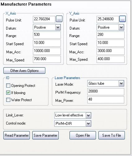
EDIT ok I have checked and I currently have this
My Y axis is close but my X axis is nowhere near
Edit number 2
Using 25.4 on both axis gives me 50mm on the Y axis and only 45mm on the X axis now I am super confused
Edit no3 I think I have found the problem I swapped the drivers and got the same so I counted the Y axis pulley it only has 18 teeth instead of 20.
That would give me 1111.111 steps/inch instead of 1000
Do you have the same "Pulses per Unit" for both X and Y axis ?
Mine are both different
EDIT ok I have checked and I currently have this
My Y axis is close but my X axis is nowhere near
Edit number 2
Using 25.4 on both axis gives me 50mm on the Y axis and only 45mm on the X axis
Edit no3 I think I have found the problem I swapped the drivers and got the same so I counted the Y axis pulley it only has 18 teeth instead of 20.
That would give me 1111.111 steps/inch instead of 1000
- J45on
- Posts: 258
- Joined: Thu Mar 31, 2011 11:30 am
- Location: Kent,united kingdom
Re: Engraving issues with LO DSP
![]() by naPS » Sat Aug 20, 2011 9:05 pm
by naPS » Sat Aug 20, 2011 9:05 pm
Here's an updated table with the value for 1/9*10,000 steps/inch.
- Microns per Step.JPG (27.58 KiB) Viewed 12953 times
- naPS
- Posts: 202
- Joined: Sat Apr 09, 2011 1:53 am
Re: Engraving issues with LO DSP
![]() by J45on » Sat Aug 20, 2011 9:13 pm
by J45on » Sat Aug 20, 2011 9:13 pm
Thank you naPS
I am going to swap the pulley with my Z axis tomorrow as I have not wired that up yet
Great charts by the way they should be stickied or perhaps made into a online calculator like barts optic and belt calculators.
I spent ages trying to measure test squares accurately this would have saved my lots have time
- J45on
- Posts: 258
- Joined: Thu Mar 31, 2011 11:30 am
- Location: Kent,united kingdom
Re: Engraving issues with LO DSP
![]() by naPS » Sun Aug 21, 2011 5:08 am
by naPS » Sun Aug 21, 2011 5:08 am
Okay, I did a quick calculation, and figured out what DPI / Scan Gap I would be at when the gap was divided by the microns / Step for my current Steps / Inch setting. At 4,000 Steps / Inch (Pulses per Unit of 6.35) I calculated out the following :
DPI / Scan Gap
100 / .254
125 / .2032
200 / .127
250 / .1016
400 / .0635
500 / .0508
800 / .03175
1000 / .0254
The pattern is pretty easy to follow there. Had a long day with birthday parties, swimming, and fighting with the kids, so won't have any time tonight to test these scan gaps out, but will give it a shot tomorrow. One thing I'm thinking about though, is when I dither a picture, it asks for a measurement. I'm assuming I enter one of these values, or whatever value I'm hoping to use from the chart. It shouldn't matter for the circle pattern type engraving I did, since that doesn't have to be dithered.
- naPS
- Posts: 202
- Joined: Sat Apr 09, 2011 1:53 am
Re: Engraving issues with LO DSP
![]() by naPS » Sun Aug 21, 2011 8:34 pm
by naPS » Sun Aug 21, 2011 8:34 pm
Okay, I made up a google docs spreadsheet from my local Excel spreadsheet. Hopefully it will help someone out.
https://spreadsheets.google.com/spreads ... E&hl=en_US
It's fairly self-explanatory. The only thing that might be somewhat confusing is the "Pulses per Scan Gap" table at the bottom. Basically, any of the entries in there that are whole numbers should be acceptable for scan gap entries for that steps / inch. For example, at 1,000 steps / inch, the scan gaps that produce whole numbers for the number of pulses between gaps are .254, .2032, .127, .1016, .0508 and .0254. These relate to DPI values of 100, 125, 200, 250, 500 and 1,000. I wish google docs would let me use formulas for conditional formatting like Excel does, then I could easily highlight entries that were whole numbers, but that's just not happening. Theoretically this should produce the best results for that particular steps / inch setting, as there should never be any overlap of the laser (assuming it's .001" in engraving situations) as there will always be a whole number of pulses in the Y direction for that particular scan gap setting. I haven't been able to test this yet, and this will definitely be different if your laser head isn't exaclty .001". Even if your laser head is .002", you can still use the chart, you just have to account for the fact that you'll only be able to use even values of DPI.
I'd consider working on a chart that will calculate these values based on varying laser head widths, but to be honest, I'm not sure we really have anything that will measure accurately enough to really make it viable. It really is kind of a do what works best for you type thing, as I'm sure everyone's optics are going to be slightly better or worse than others, and some folks will be better at focusing the beam and all that jazz. So, this is really just more of a theoretical idea of how good your system can perform if it's basically perfect.
- naPS
- Posts: 202
- Joined: Sat Apr 09, 2011 1:53 am
16 posts
• Page 2 of 2 • 1, 2
Return to Commercial DSP CO2 Laser Engraving/ Cutter Controller
Who is online
Users browsing this forum: No registered users and 14 guests