Getting More Power and Cutting Accuracy Out of Your Home Built Laser System

I have developed an inexpensive control system (less than $70) that can be used to both get more cutting power out of a DC discharge laser and significantly improve cutting accuracy for home built laser systems. The control system implements a control technique known as Pulse-Per-Inch (PPI) control. PPI control involves pulsing the laser every time the head travels a certain distance. PPI control allows a CNC laser to produce consistent cuts at the same power level setting over over a wide range of speeds. In effect, pulsing the laser as a function of distance along a cut decouples the power input to cut from the speed that the head travels. Therefore, the speed and acceleration of the CNC system have minimal bearing on the cut characteristics. Furthermore, the unique transient rise response of a DC discharge laser allow PPI to deliver more power to a cut in comparison to the same laser system with just on/off control.
Background and Motivation
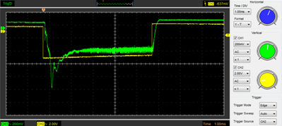
A while back, I was active on a forum in which we were discussing the time it takes to turn a laser on and off and how that relates to engraving control. One of the forum members from Full Spectrum Engineering posted a high-speed intensity spectra for the cheap DC discharge lasers that we use for DIY laser cutters. I was quite surprised by the spectra. I expected to see a nice exponential rise to set power level, but what we saw was a rapid rise to a very high power level (nearly double the set value) followed by an exponential decay to a set value. The Spectrum in question is shown below (credit for the spectrum rests with Full Spectrum Engineering). The yellow square wave is a 5ms pulse sent to the laser power supply. The green spectra is the intensity spectra of the laser. For whatever reason, the magnitude of the spectra is upside down (I think the ground and signal leads were reversed), so on for the digital signal and higher intensity for the laser power spectra are down rather than up. Anyhow, the spike in intensity is caused by the necessity voltage to start a plasma in a DC Laser. The laser power supply generates a very high voltage to start the plasma which is stored in a capacitor. When the signal comes to turn on the power, the power supply dumps this charge into the system and then supplies a nominal (still very high) voltage to sustain the plasma once it is on.
DC Discharge Pulse
The spectra got me thinking about a PPI control system that Ben Jackson, another member of the forum, had implemented with EMC. PPI control is used by big companies like Epilog and others for vector cutting. The thought came to me that a short pulse of 2-3ms would result in an average power output that was significantly higher than the output of a constantly on system. Further, the duty cycle is generally much lower which will allow the laser to operate much cooler. This allows a DC laser to effectively operate at much higher power levels than it is rated for without causing damage to the system.
There are also accuracy benefits to using PPI control. To get great results with vector cutting, one has to very tightly control the power density going into the material no matter where the laser head is or what its velocity, or acceleration is. If this is not done, one can get very inconsistent results. The inconsistencies are mainly related to power density variations causing variations in kerf width and/or overheating materials which cause charring/melting/burning. When a CNC machine encounters a corner or a sharp curve, it has to adjust the speed of the head to smoothly accelerate into and out of the curve or corner. For laser systems, there is no tool pressure and the head is fairly light so the accelerations are very fast and almost unnoticeable. Even so, the time it takes for a laser to cut/expand kerf is orders of magnitude faster than the time frame needed for acceleration. This means that tight control of the laser at all times during a cut is needed for the best results. Perhaps the most noticeable problem most people encounter with a home built laser system is what looks like a tiny drill hole at the start and stop of a cut. The problem is particularly noticeable for those who use standard CNC software (like Mach 3 or EMC) to control the laser and is caused by a delay in the control system when it processes the on/off command before/after motion starts/stops. The delay is only on the order of ~5-10ms or so (almost unnoticeable), but that is enough for the laser to expand the kerf as it sits stationary. Lead in and lead outs can help this problem, but one does not always have room for the lead in with certain parts or there may be so many cuts in a file as to be impractical. An example would be a scroll saw pattern. A CNC laser is ideal for this kind of artwork, but the drill hole at the start/stop of a cut can be visually unappealing and adding lead in/outs for thousands of cuts is quite tedious, if there is even room to do it. There are relatively inexpensive laser controllers out there (FSE and DSP) that have better laser control and eliminate this, but they range in price from $400 to$500 and they can’t handle g-code files. Further, for engineered parts, the tolerances can be improved by a constant kerf width at all times.

Epilog Elite Series Lasers www.epiloglaer.com
It is for these reasons that the “big guys” in the industry use PPI control for vector cutting. By pulsing the laser as a function of the distance traveled, it strongly couples the sum power applied to the material being cut to distance along the cut path rather than the time the laser is on. This decouples the power density from velocity of the head, which is key to achieving consistent cuts. If the pulse were instantaneous, there would be no coupling to velocity in this method as long as the laser could supply the frequency and the power level needed to make the cut. In reality the pulse has a defined time width which means that the travel velocity does affect the cut, but to a much lesser extent. In this way, a great number of discrete events produce a high quality cut which are almost completely decoupled from the time derivatives of position.
Control Strategy
To do this, one has to accurately know the position of the laser head at all times. Without going to the lengths of installing a linear encoder on the axis, one can do this by tracking the pulse and direction signals to the stepper motor drivers. This could be done in the motion control software (ex: Mach 3, or EMC). However, this strategy places extra computational burden on the controller and can lead to inaccuracies if the controller does not operate in a truly real time fashion or if there are real time delays. Further, one would need a differently developed solution for each controller which is a lot of work and may not be possible in every case (such as with the light object controller). However, every controller has to produce a step and direction signal in the same way which get sent to a stepper driver, so this is a good place to track position from as it is universal and truly real time. In my case, I use Mach 3 with a USB Smooth Stepper (SS). The SS is capable of producing step pulses at about 2 MHz which is significantly faster than most common controllers that use a parallel port. With the standard setup of a 2.X system with 0.9o steppers and 16x micro-stepping, a 2MHz pulse rate amounts to about 70 m/min travel speed. This is faster than I really ever run the system now, but these are common speeds for engravers that are higher power than my machine. I have a 40W system and will likely upgrade to a higher power source as I start to develop an engraving solution.
There are a couple ways to count pulses this fast. One can use a micro-controller (MC) directly or dedicated set of binary up/down integrated circuits (ICs) with a MC. To use a MC directly, one would have to be able to pole the pulse and direction the signals at a minimum of 4x faster than the signal frequency. That means about 8 MHz in my case. For most common MCs, it takes about 20-50 machine code lines to read an input pin, do a basic comparison/calculation, and set an output pin (or set of). One could also use a pin based interrupt to do the counting. However, at 2MHz pulse rates, this means that there are fewer than 8 machine code lines between pulses to do any operations related to the math it takes to set the pins as well as actually setting the pins. This is simply too fast for a single core MCs to keep up with running at sub-GHz speeds and expect the MC to be able to reliably do anything else but simply indexing a counter. To make this feasible with cheap and easy to use MCs (like an AVR/Arduino), one has to alleviate the counting burden from the MC (ie: using a set of ICs to count for the MC). Fortunately there are many MCs that are cheap and have a plethora of digital IO to read the 17 & 16 bit binary numbers produced by the ICs to count all the pulses on the x & y axes respectively. As long as the MC can execute its loop through the calculations to set the laser within a 500 microseconds, then everything is alright. The MC is free to pole the counter signals at will and at the time it checks it, the position is guaranteed to be real time and up to date (as long as the ICs are rated for faster clock speeds than the stepper pulse rate). The MC can then act on that information however it needs within a few (to tens) of microseconds (depending on your code efficiency), which is plenty fast enough as the laser can’t even turn on within 500 microseconds.
Hardware/Software Implementation
Now that the control strategy is understood, I will move on to how this is implemented in hardware and software. The hardware is fairly simple and cheap. The heart of the IC counter is the MC14029B by ON Semiconductor. I got them from digikey for about $0.70 a piece. They are 4 bit binary/decade up/down counters with a reset and direction pin and have a carry in and carry out pins so they can be linked in series to make larger counters. To count all the pulses at max micro stepping, it will take 17 bits on the x axis and 16 bits on the y axis. As an aside, one doesn’t need to count all the pulses and could probably get away with an 8 bit counter, but I want to use this setup for engraving as well which means I need absolute position tracking and not relative, so I went ahead and made the counters big enough to count all the pulses. That means I need 5 on the x and 4 on the y for a total of 9.

Binary Counter Circuit Diagram
The ICs are through hole and have sockets on the board. The pin headers are 26 pin and 34 pin on 0.1” pitch. This allows a common ribbon cable to connect to the board. The power terminals are screw terminals.
The 26 pin header is used to listen to the incoming step, direction, and limit switch signals that come across the 25 pin parallel port from the CNC controller. The SS comes with a 26 pin ribbon cable that is terminated in a 25 pin D-Sub connector. I put a 26 pin IDC connector in the middle of that cable to connect to the header on the left side of the above figure. I actually recommend that people “snoop” this way. It was the cheapest way to gain access to the signals without cutting the lines. Two 25 pin D-sub connectors and a short length of ribbon cable can be purchased for about the same price as a regular 25 pin D-sub cable. You lose shielding, but I found that you don’t need it. The stepper pulse from each axis goes to the clock of each IC. The direction signal is tied to the up/down line, and the limit switch is tied to the reset pin. The input pins for the reset value are tied to ground so that each time thel imit switch is hit, the counters initialize to zero. There are a total of 35 pins to read for input from the counters plus one pin to read for the laser signal for a total of 36 to pass to the MC. The circuit can be routed onto a 2 inch by 2.5 inch board.
Example Hardware Layout
I chose to arrange the output pins in order to make troubleshooting easier and the board layout simpler. However, that means that the cable coming from the board needs to be rearranged so that the output pins meet up with ports on the MC in a logical manner. The port/pin arrangement for each MC is different and will require a cable to match, but that is relatively easy.
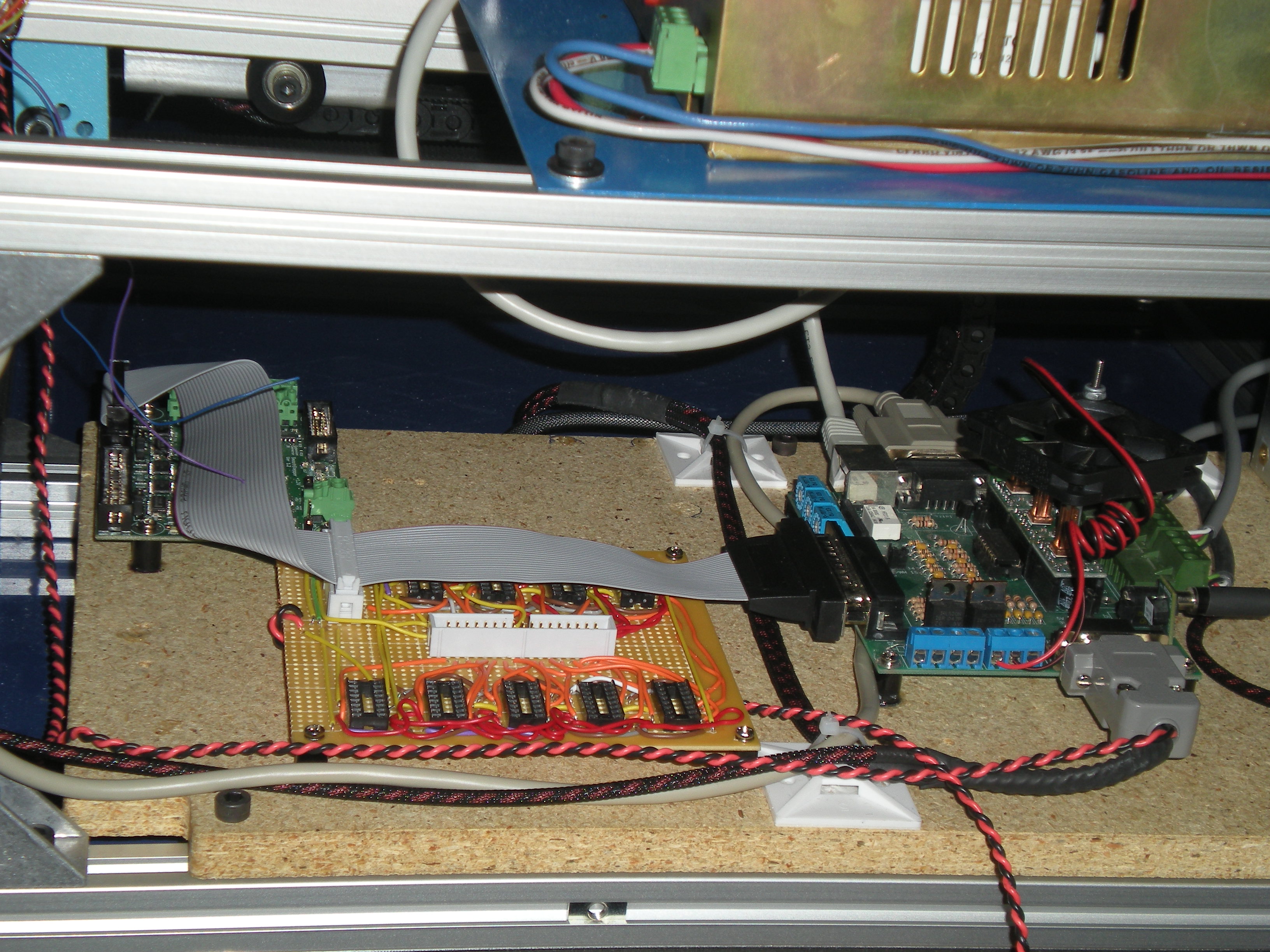
Counter Board Installed
The proto-board is significantly larger than a PCB would be, but it fit just fine anyhow. I am very glad that I built a proto-board first because I had originally tied the Binary/Decade pins to high rather than low as I misunderstood the datasheet.
The MC I chose to use was an Arduino Mega. I chose this because I had it laying around and it had enough IO to read the pins, not because it was particularly optimal for the design, though it was more than sufficient. I mounted the board on the underside of the LPS shelf so it would be out of the way.
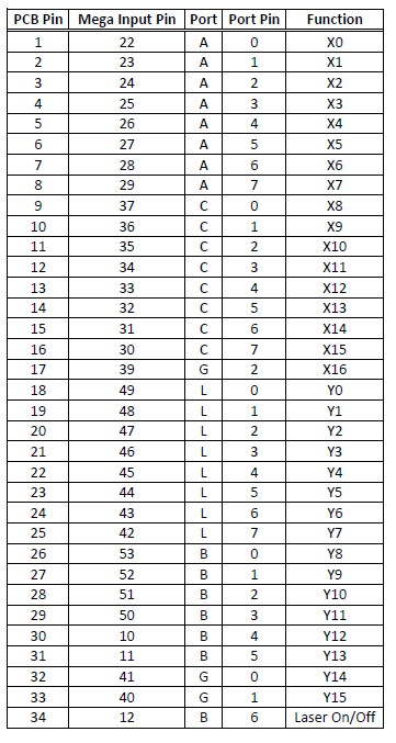
Mega/PCB Cable Connection Table
The quickest way to read a large set of digital pins is to read an entire port at once. This only takes one machine code line. The Mega has groups of 8 pins per port, which means that I have to read a minimum of 5 ports to get all the information. Newer MCs (ARM based) have 16 pins per port, which means one would only have to read 3 ports. The strategy here is to group the binary pins in order so that they only have to be bit shifted and added to make the large number. The following table shows how to order the pins for the cable to connect the hardware to the Mega. I have a pin crimper so I split the wires apart, stripped the ends and put them into 0.1” pitch pin holders to connect the pins to the board.
If you have been following my buildlog, you would see a difference in this order in that I originally had the laser set tied to pin 13, but this would make the laser flash on reset and data transfer because pin 13 is also tied to an LED on the board that flashes with those events. To keep the laser off and safe, I switched the pin to 12. Also, you may be wondering why I didn’t use all of B for an input for Y. First, there is the pin 13 issue, but also I wanted to use an output that wasn’t tied to the X axis group to switch the laser on/off for engraving. Further, the physical grouping made this easier.
So now let’s discuss the code. The first thing to check is if the laser cmd in pin is high. If it isn’t, the laser set pin is set to low. If it is on, the next thing to do is check for motion. If the head is moving, proceed. If it isn’t, the MC will set the laser to off. If there is motion and this is the first time through the loop that the laser pin went from 0 to 1, then immediately set the laser to on and start the timer. When the timer reaches a given time, the MC will set the laser back to off. Now the MC just calculates the distance since it set the last laser on state. When the distance is greater than a given value, it will reset the timer cumulative distance value to zero.
The code can be found on my github sit: DirksGitHub
Testing
With that, the control system is functional, so let’s talk about some results. I set up some tests to cut paper. I wanted to use paper because it is notoriously difficult to cut well with traditional means. It is very thin so if you heat it too much, it can easily catch fire. However, with a pulsed cutting system the heat is managed and this is not a problem. Further, any overheating is magnified as poor quality cuts.

PPI Test 1
I set up 3 tests which would show the results of varying the PPI setting, the feed rate, and the pulse width. First, the PPI was varied from 25 to 800, doubling each test. The cuts were 1 inch long , the pulse width was set to 3ms, and a constant feed rate of 400mm/min was used. You can see that it is actually calibrated correctly. There are 25 spots cut into the 25 PPI line. There should be 26, but it is likely that Mach 3 didn’t give the final pulse needed to get the last laser pulse to switch on or that the number of pulses per inch is slightly off in the MC program. There is probably a way to fix that in the code, but for higher PPI settings, it doesn’t matter if one pulse is missing at the beginning or end. The 50 PPI setting is indeed double the pulses and they line up well. The 100 PPI is just barely continuous and the individual dots just barely overlap. That means that the laser spot is about 10 thousandths of an inch across. I might be able to do a little better if I turned down the laser power and worked a little harder at finding the correct focus, but that isn’t bad for paper. The 200 PI line is the first one that looks to be continuous. The 400 and 800 PPI lines look progressively smoother, but get wider as the PPI increases. You can see there is a little disturbance in the middle (particularly noticeable in the 800 PPI line). That is the result of one of the cross-members in my table.

PPI Test 2
The second test was to vary the feed rate while keeping the pulse width and PPI constant. The image shows the results of varying the feed rate between 600 and 8000 mm/min. The pulse width was set to 3ms and the PPI was set to 50. The lower set shows the feed variations between 600 and 4000 (actually, between 400 and 4000, but I wrote over the first line by accident). You can see that the 600 to 1200 look to be identical. The rest of them up to 4000 seem to be a bit off with the endpoint. They have the same number of pulses, but the endpoint (right side of the line) seems to be shifted in length a bit. I don’t think this is a problem with the controller, but the result of backlash in the mechanical system. I will have to look into this further though. I have noticed variations in my parts up to about 20 thousandths so this may explain some of this. I suspect that the backlash is coming from an imprecise mate between the drive sprocket and the toothed belt. It may not be hard (or expensive) to make this system into a servo based system. Epson printers use an encoder filament strip with a LED/phodotiode set to control the position of the print head. It should be possible to use a system like this to provide feedback to the stepper controller or completely replace the steppers with a DC motor drive with an H bridge motor controller. Either of these strategies will compensate for position inaccuracy.

PPI Test 3a
The last test was to vary the pulse width and keep the feed rate and PPI the same. The feed rate and PPI were set to 400 and 50 respectively. The lines in PPI Test 3a are pulse widths between 1ms and 10ms. 1ms is too short to cut through the paper, but it does mark it. 2ms results in a cut, but very fine. 3 and up cuts with progressively larger diameter and darker, but they don’t show much evidence of smudging (that is the holes seem to be round). It’s hard to say, but the 10ms line may show a bit of smudging starting to happen.

PPI Test 3b
The bottom 9 lines in PPI Test 3b progress from 20 ms up to 180ms by 20ms intervals. The top line is 1000ms and is basically full on. The 40ms line happened to be right on top of a cross member in my table which reflected the light and burned it out unevenly. The second half of the line was fine though. You can see definite smudging in the dots. At 80ms, the dots are fairly well connected. Any longer time has fully connected dots. The kerf width gets quite a bit wider and less uniform.
While this test is informative and demonstrates the effect of longer pulses, there is no need to use a pulse width longer than 3ms. 2ms may be better.
There also seems to be some inconsistencies in producing the first and last pulse. This isn’t very concerning though. Missing the first or last pulse in a cut with a high PPI setting doesn’t amount to much. That said, I will work on fixing the code so that this doesn’t happen. The big thing is that the laser is not on when the head isn’t moving. If there is an error, I would prefer that the error falls on missing a pulse rather than producing an on signal when the head isn’t moving.

Scroll Saw Art Present for My Sister
I developed this control strategy to do scroll saw work and make Christmas presents for my family and friends this year. The control strategy allowed me to avoid the drill holes, use a free control program (lazy cam) to produce the g-code as I didn’t need lead in/outs (which allowed me to keep my sanity as well as there was about 500 cuts to make). As a matter of record, the lower whisker in the upper group on the right side thins out to about the thickness of a piece of paper. Without this control strategy, I couldn’t have cut that. The edges also turn out with a very nice light brown color. This is 1/8” baltic birch plywood. I found that the best settings are 400PPI, 400mm/min, 3ms, and 100% power. The PPI setting to get a continuous cut is much higher for thicker materials because the kerf at the bottom of the cut is significantly narrower than at the top. I understand that this is in part due to self focusing of the laser in the kerf. Too much lower PPI results in non-continuous cuts.
Test Summary
The PPI implementation worked very well with the exception of occasionally missing the first and last pulse which will have to be investigated. This problem is not noticeable with high PPI settings (high enough to create a continuous cut). Cuts using PPI are much more controlled with uniform kerf and no burn in and burn out marks when the laser head starts and stops. Further, tests in wood show that the amount of burning in the cut is much lower and the sides of the cuts are much lighter. That said, there is a certain amount of roughness on the sides of the cut with lower PPI settings. With high PPI settings, this is barely noticeable.
Future Work

Cyber Cortex (www.fabuloussilicon.com)
So where do I think this will go? I think this will migrate to an FPGA controller. There are several FPGA based controllers on the market for very little cost. Bart Dring told me about the Cyber Cortex AV by fabulous silicon. FPGA’s are amazing! You can basically program the controller to be any transistor based IC you want. I could fit the whole counter board developed here and 3 or 4 Arduino’s on one chip. I will eventually migrate this project to the Cyber Cortex and implement the engraver on that as well. I currently use another Arduino Uno to do modbus IO for the system. That can also get rolled into an implementation of an FPGA controller. This means that the open source community could have a PPI controller, an engraver, and a modbus IO for under $150. As I make progress with this project, I will continue to post results and make the code available to anybody who wants it.
Acknowledgements
I would like to thank Bart for providing the opportunity for me to share this bit of work with the great user community we have here at buildlog and also for giving us such a great base of a CNC laser system to have a bunch of fun with. I would also like to thank Ben Jackson for giving me the idea to use binary up/down counters and for reviewing some of my design work. Finally, I would also like to thank my friend Justin Weber for being a sounding board for my ideas and for being just an overall great friend.
Buildlog.net Editor’s Note
Thank you to guest blogger Dirk Van Essendelft for this post. Dirk is a Chemical/Biochemical Engineer from Morgantown, WV. Outside of his work as an research scientist for the National Energy Technology Laboratory, Dirk has interests in woodworking, robotics, CNC Machining , and model building.


[…] configuration file includes a custom HAL component that does PPI (pulse per inch) control. With this configuration, I have three "knobs" I can turn to adjust how the laser cuts or […]
Wow, looks like you read my mind, I was pondering this PPI issue with my home-brew laser just this morning.
Would you be able to make the Eagle SCH/BRD files available for the counter board?
Thanks,
Steve
Has there been any progress on a PPI controller since 12/2011? Are any of the designs/code being shared? Ifo so, where could I obtain them?
Thank you!
-charlie
Sir I have epilog laser Legend 32EX, This old model 2004 or 2005. Epilog company make this x axis encoder strip and y axis encoder strip, Now our laser engraver have a problem in Y axis encoder strip. I change this too much time. But working for some home. again bad. Now epilog company make laser engraver without y axis encoder strip. I too much write to epilog company to give me idea to do without encoder strip. but not give me any information.
Now I want our laser working in Y axis without y axis encoder strip.
Now epilog new laser engraving and cutting without encoder strip (y axis )
[…] The folks at the Lansing, Michigan hackerspace built themselves a 40 Watt laser cutter. It’s an awesome machine capable of cutting plywood and acrylic, and is even powered by a RAMPS board, something normally found in 3D printers. They wanted a little more power out of their 40 Watt tube, though, and found pulsing the laser was the best way to do that. […]
[…] The folks at the Lansing, Michigan hackerspace built themselves a 40 Watt laser cutter. It’s an awesome machine capable of cutting plywood and acrylic, and is even powered by a RAMPS board, something normally found in 3D printers. They wanted a little more power out of their 40 Watt tube, though, and found pulsing the laser was the best way to do that. […]