The Polar Coaster – A Drink Coaster Drawing Machine

I designed this machine to draw custom, round drink coasters. I already have a laser cutter for square coasters and I wanted to try something unique for round coaster.
The Base
The base of the machine has two stacked 5mm bearings in the center for the bed to rotate on. There are (3) 3mm bearings on the bed perimeter that provide support and keep it level. They have little shafts that snap into the base.

The Bed
The bed is a 156 tooth GT2 pulley. It has little springy fingers that grip the coaster when it is on the bed. The bed connects to the motor pulley with a closed loop belt.

The Radial Arm.
This is a belt driven, cantilevered arm that uses 6mm shafts and linear bearings. The belt is a cut pieces with the ends clamped at the carriage. It has a slotted mounting hole that lets the arm rotate. The pen must be adjustable to get to the exact center of the coaster or the drawing will be distorted. There is a limit switch on the top. This is the only axis that needs to be homed. To setup the machine you home it and jog the pen until it is exactly over the center of the bed. You then set the work zero for X (Gcode: “G10 L20 P0 X0”). This only needs to be done once. If you use different types of pens, the center should be rechecked.

The Z Axis
The Z axis uses a micro servo and a cam to control the height of the pen. The firmware is setup to only have (2) Z positions, pen up and pen down. It uses 3mm rods and tiny little 3mm linear bearings. There is a compression spring on one of the rods that applies a little pressure to the pen, and allows the pen to float a little on uneven coasters.


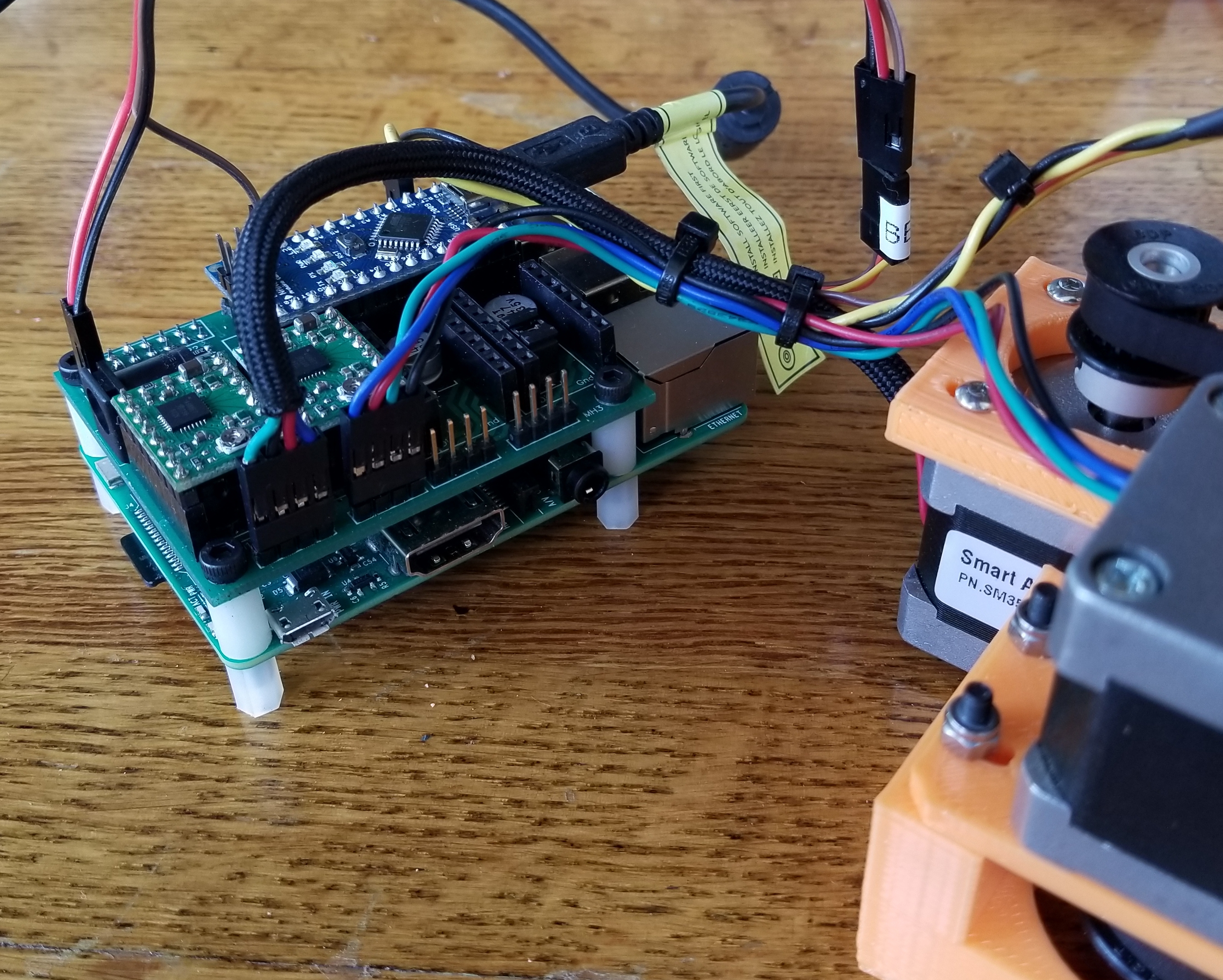
The Controller
I used my Grbl HAT controller. It is a bit overkill for this project but works perfectly. It is attached to a Raspberry Pi in this photo, but I have not been using the Pi in this project yet. I just connect directly via USB.
Kinematics and Pre-Processin
See this blog post on how it was done. The pre-processor is written in C#, but it is rather simple and you could probably read the source file and convert if you cannot deal with C# on Windows.
Firmware
I use a modified version of Grbl 1.1f. Grbl does not support servos, so I needed to hack that in. I used the PWM that is normally used for the spindle speed to control the servo. I turned off the variable speed spindle option and streamlined the spindle functions to the bare minimum I thought Grbl needed. I adjusted the PWM parameters for use with a servo and added pen_up() and pen_down() functions. I tried to put as much of the custom code into one file spindle_control.c. I had to add a few lines in stepper.c to look at the current machine Z height and apply the correct pen up/down function.
CAM
You can use anything to generate the gcode that works with Grbl. The pen will go up when the Z is above zero and down when it is below zero. Therefore, you want the Z movement as short as possible to speed up the drawing and not have the pen dwell on the material and bleed. I make the depth of cut 1mm and the z clearance 3mm.
CAD Files.
The design was done using PTC CREO 3.0. A STEP version of the design is linked at the end of the post.
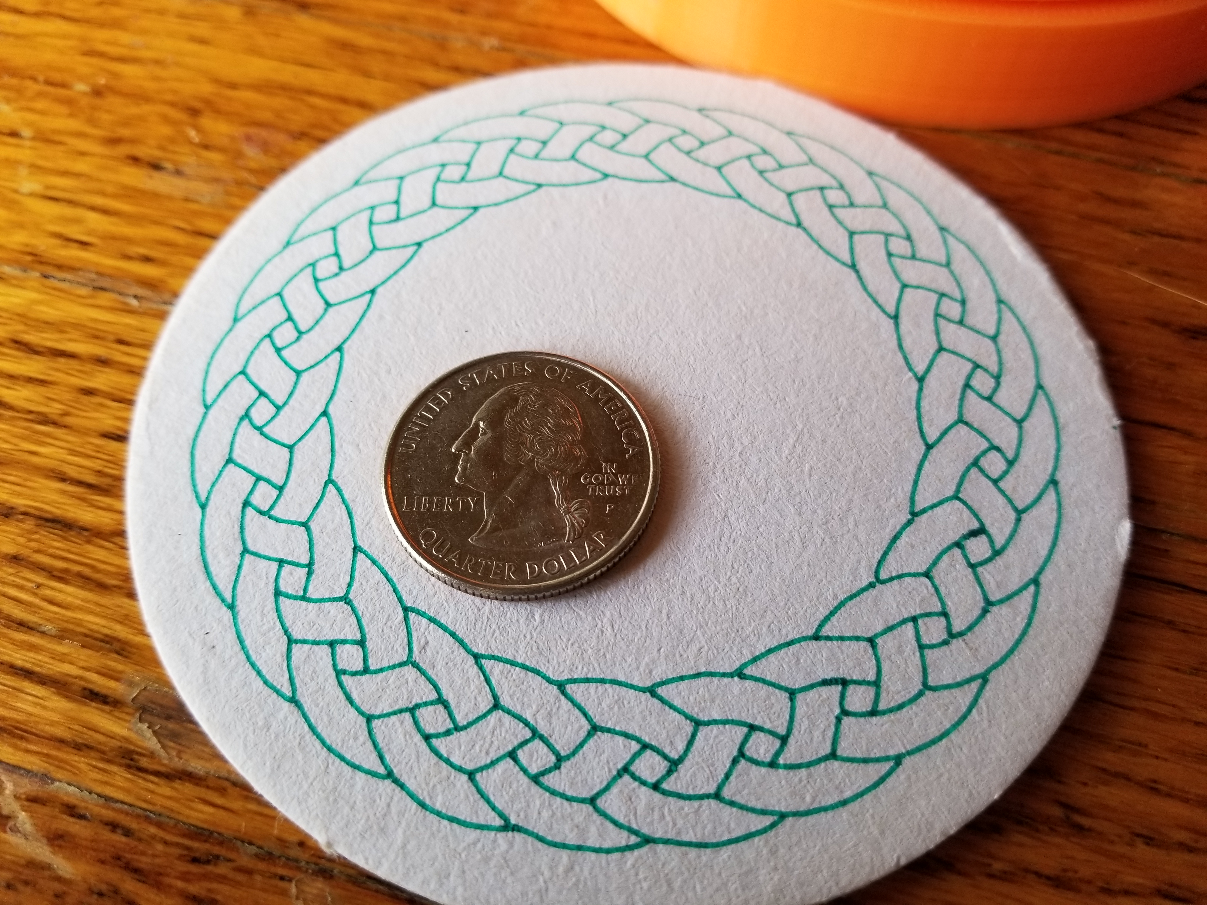
Performance
It does a great job. Here a recent coaster. This was done from a rasterized bitmap image found online (searched: circular Celtic braid).
Here is a Fat Tire beer themed coaster.
Coasters are made to be super absorbent, so larger tipped felt pens tend to bleed a little too much. I like to sketch with Micron pens and the thinner ones really work well on this machine.
Build You Own?
The build is not difficult, but covers a lot of areas. You should know how to work with STEP files and compile firmware.
The design is open source with no commercial restrictions, so feel free to use any part of my work. I found most of the parts on Amazon and eBay. I bought the belt from Stock Drive Products. The polar motor pulley is 36 tooth and the arm pulley is 20 tooth. Cutting the shafts requires an abrasive cutoff wheel.
Please post any questions in the comments section and I will try to address them.
Links


Awesome machine!.
Minor issue: all links seems to point to CAD zip file.
Ruwan
Thanks Ruwan,
Links should be fixed.
Hallo,
very nice machine. I don´t understand how to use the Pre-Processor. Must I compile (is there a EXE file) it and how it works?
Is it possible to open an existing gcode file and output the converted one to send it with my standard gcode sender?
Is the only modification that you make to the grbl firmware the PWM modification? If I had a normal Z-Axis can I use my standard grbl?
Thank you in advance for your answers.
Ulrich
Ulrich,
The pre-processor is source code for Visual Studio 2017. You can run it in visual studio or compile an exe.
If you use a stepper for Z you do not need to change Grbl.
I’ve got a RAMPS set lying around. I figure I can use that for this, but honestly I don’t have a whole lot of experience with firmware and such. Is it possible? Would it take me forever to figure out on my own?
A RAMPS board is overkill, but there could be many ways to go on this.
1. You could use the Grbl/Mega fork of Grbl. The pen servo would need to be added. It is “easier” on a Mega because you have more PWM resources, but the code (registers) is a little different. As I recall the RAMPS has a few servo connectors.
2. You could try a 3D printer firmware like Marlin. There were made for RAMPS.
Either way, the level of difficulty depends on your coding experience. If you are good with firmware, it should not take too long. You could always buy my board from Tindie. You probably already have the stepper drivers.
Hello very nice machine, what would be the steps to turn it into a polar 3d printer.
Polar 3D printers exist and they are very nice. The build areas are big compared to the printer and the head only has to have half of the travel of the bed size.
1. You would need to create a stepper motor controlled Z axis and put an extruder on it.
2. The extruder gcode would need to be coordinated with the actual length of travel.
3. The crude feed rate compensation I did is probably not good enough for 3D printing. If you did #2, I think you would have all the info you need for feed rate compensation.
If you build it and need help with a gcode converter, I would be glad to help.
Ref: http://about.polar3d.com/printer/
I don’t understand, where is python involve in this project ?
Kortak,
The CAM programs that generate the gcode (motion instructions) only work for Cartesian (rectangular) moves. The gcode needs to be converted to a Polar coordinate system before it can be used on this machine. See my other recent blog posts on this subject for more information.
Which bearings where used on the base? do you have the dimensions or names?
Tal,
The bearing is a 625-2RS. The dimensions are 5mm-16mm-5mm
From the video it like the polar drive belt has part number 6R51M186060. I found it on the SDP/SI web page:
http://shop.sdp-si.com/catalog/product/?id=A%206R51M186060
6mm x 372mm (186 teeth). Is that correct?
That is the belt I used. It is a little bit of a tight fit, but works fine.
Thanks bdring,It is a very nice machine!
I have build my own one,I converted the code, but still can not work properly, the image is distorted.
Can you send me the test Gcode just like the image in Youtube.
And is the distance of zero(X) point to the center point 45mm?
Hi bdring.
Here is my grbl setting,and I test the 40mm square_polar Gcode,It is distorted, looks like the X axis moves too little.
2017/09/09 16:20:58 – Grbl 1.1f [‘$’ for help]
2017/09/09 16:20:58 – $0=10
2017/09/09 16:20:58 – $1=25
2017/09/09 16:20:58 – $2=0
2017/09/09 16:20:58 – $3=0
2017/09/09 16:20:58 – $4=0
2017/09/09 16:20:58 – $5=0
2017/09/09 16:20:58 – $6=0
2017/09/09 16:20:58 – $10=3
2017/09/09 16:20:58 – $11=0.010
2017/09/09 16:20:58 – $12=0.010
2017/09/09 16:20:58 – $13=0
2017/09/09 16:20:58 – $20=0
2017/09/09 16:20:58 – $21=0
2017/09/09 16:20:58 – $22=0
2017/09/09 16:20:58 – $23=1
2017/09/09 16:20:58 – $24=25.000
2017/09/09 16:20:58 – $25=500.000
2017/09/09 16:20:58 – $26=250
2017/09/09 16:20:58 – $27=1.000
2017/09/09 16:20:58 – $30=1000
2017/09/09 16:20:58 – $31=0
2017/09/09 16:20:58 – $32=0
2017/09/09 16:20:58 – $100=160.000
2017/09/09 16:20:58 – $101=160.000
2017/09/09 16:20:58 – $102=160.000
2017/09/09 16:20:58 – $110=5000.000
2017/09/09 16:20:58 – $111=5000.000
2017/09/09 16:20:58 – $112=5000.000
2017/09/09 16:20:58 – $120=10.000
2017/09/09 16:20:58 – $121=10.000
2017/09/09 16:20:58 – $122=10.000
2017/09/09 16:20:58 – $130=300.000
2017/09/09 16:20:58 – $131=200.000
2017/09/09 16:20:58 – $132=50.000
Great, it is done,it is working now!
I make mistak of the (X)zero point an the (Y)steps.
$101=78?
Pepperl,
I am glad to hear your machine is working.
I needed to calibrate my polar axis. The math suggested one steps/mm but when moving 360 units it was a little off a full circle. I tweaked the number a little until I was getting consistent motion.
I had a little trouble finding that 186 tooth belt and the site I did find has a minimum order, so I thought printing one first. Here’s the design I came up with:
https://www.thingiverse.com/thing:2528419
I’m also remixing some of the parts so it might work with with the NEMA17 motors I have in my junk box.
BobM,
Thanks for making that belt. I might try printing one. There is no load on these belts and they might actually be more compliant to the 3D printed pulleys.
NEMA17…most of my choices are based on what is laying around too.
can u send me the picturial representation of this cnc machine to how to make it
Right now the only file I can provide is the STEP file linked in this post.
Hello!
Can you tell me the codes and the dimensions for the little support bearings?
Thank you
The bearings are 3mm ID, 10mm OD and 4mm Thick. Any bearing will do, but the ones I used are know as 623-2RS bearings.
how about the pen belt? the big belt is 6mm x 372mm (186 teeth).
Thank you
Yes,
I bought the 186 tooth x 6mm belt here.
http://shop.sdp-si.com/catalog/product/?id=A_6R51M186060
The belt is slightly tight so 188 teeth would work as well. Some people have printed belts as well, but no reviews of that on this machine yet.
This looks like a lot of fun and great design. What program do you use to control the polar printer? I’m familiar with tools for 3D printing, but this is new to me. I plan on using your controller and Arduino Uno. Thanks in advance. Bryan
Hi , i made this amazing project but i cant understand how to process the Gcode..
can you explain how to work with the processor?
thanks for sharing this project.
Ofir
You no longer need to process gcode if you use the latest Grbl_ESP32 firmware.
https://github.com/bdring/Grbl_Esp32