Using Grbl’s Spindle PWM to Control a Servo
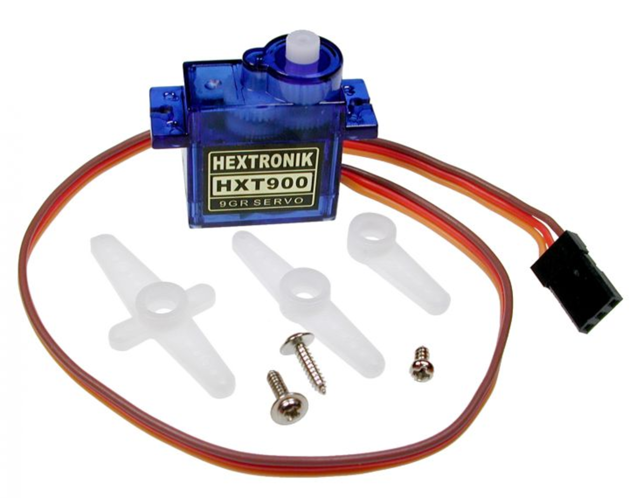
While I am waiting on some parts to arrive for a pen ‘bot, I started investigating ideas to control it. It will be using a hobby servo for pen up/down. Servos work great for things like this because they are easy to integrate and don’t need to be homed. They always know where they are in rotation.
I am probably going to use Grbl and it outputs step and direction signals for motion. A servo requires a PWM signal. Since the spindle already uses PWM to set speed, this seems like a good place to start hacking. A PWM signal has a frequency and a duty cycle. The frequency is how often the signal repeats and the duty cycle is how long the output signal is logic high (the rest of the time it is low). Servos want the signal to repeat every 20ms (50Hz). They want the duty cycle to be 1m long at one end of the rotation and 2ms at the other end.
- 0 degree duty cycle = 1ms
- 180 degree duty cycle 2ms
- Frequency 50Hz (20ms)

PWM is a peripheral found on most micro controllers including Arduinos. They use the timers built into CPU. You setup a few registers and the PWM runs independent of of the code. The spindle is using timer2. All other timers are being used by other Grbl functions (on Unos), so they are not available. Timer2 is an 8 bit timer so it can only count up to 255. To set the duty cycle you set a “compare” number that is 0-255. At the beginning of the cycle, the output will go high and the timer will begin counting. When it reaches the compare value the output goes low. When it reaches 255, the cycle starts over again.
Issues
- Resolution: Since the servo’s duty cycle range ( 1ms to 2ms ) is only a fraction of the frequency (1ms/20ms) , we only have 1/20 of the 256 counts at best. That is going to limit our resolution, but we only care about a rough pen up and pen down in this application.
- Frequency: You don’t get to pick any frequency on Arduinos. You are limited to certain fractions of the CPU clock. The allowable fractions are 1/1, 1/8, 1/64, 1/256 & 1/1024. We need to pick one that is close to getting us to 50Hz.
Setting the frequency.
The formula for the setting the frequency is..
Freq = F_CPU / (Prescaler * TimerResolution) Eq #1
- Freq: Our desired frequency of 50Hz
- F_CPU: This is the frequency of the CPU. For most Arduino that is 16Mz
- Prescaler: This is that fraction mentioned about.
- TimerResolution: In our case this will be 256
This can be rewritten as this to find Prescaler…
Prescaler = F_CPU / (TimerResolution * Freq) Eq #2
Prescaler = 16,000,000 / (256 * 50)
This yields 1250 as the desired prescaler. This is not an option so we pick the closest one of 1024. If we plug that into Eq #1, we get 61Hz. That is close enough.
Determine the duty cycles.
We need to determine the compare values for each end of the servo rotation. A unit of compare value is often called a “tick”. Each “tick” of the timer is…
Tick = 1 / (F_CPU / Prescaler) Eq3
Tick = 1 / (16,000,000 / 1024)
This yields a tick length of 0.000064 seconds. We then determine how many ticks are needed for each end of travel.
- 0 degree = 0.001 / 0.000064. This yields 15.6 Ticks which needs to be rounded to 16
- 180 degrees = 0.002 / 0.000064. This yields 31.25 Ticks which needs to be rounded to 31.
Setting The Resisters.
You need to deeply dive into the datasheets for these, but I’ll briefly explain them here.
TCCR2A = (1<<COM2A1) | ((1<<WGM20) | (1<<WGM21));
TCCR2B = (1<<CS22) | (1 <<CS21) | (1<<CS20);
OCR2A = 31;
- First line: TCCR2A (Timer/Counter Control Register A for Timer 2). WGM20 & WGM21 (Waveform Generation Modes) are setting the mode to Fast PWM. The COM2A1 bit tells the CPU to clear the compare value when reached.
- Second line: TCCR2B (Timer/Counter Control Register B for Timer 2) This sets the Clock Select bits to the value needed for a 1024 prescaler .
- Third Line: Sets OCR2A (Output Compare Register A for Timer 2) to 31, which is the 180 degree value determined above.
Note: Grbl uses some aliases for the register names to make the code a little easier to read and more universal between Uno/Mega, so keep that in mind when reading the actual code.
Testing:
I loaded the firmware and hooked the output to my Saleae Logic 4 logic analyzer.
Here is the output at at the 0 degree rotation 1.087ms @ 61.07Hz

Here is the output at 180 degree rotation. 2.047 @ 61.07Hz

The Firmware.
The firmware is in this GitHub repo.


What an excellent article! … your code works extremely well 🙂
I have written a simple post-processor for inserting the necessary GRBL pen-lift commands into existing g-code.
This code runs under “processing 3” and will be available shortly in an article I am about to publish on
https://www.instructables.com/ … just type LINGIB in the search bar to find it.
Thank you for making your code available.
Best explanation when I needed the most. Just finished building my plotter and was looking for the suitable grbl mod for servo.
Thanks a lot
I don`t get it. I get “else after else” error. Is it possible to get a PWM control for an RC type of spindle with this? I have no clue about coding.
Hey lingib,
On the http://www.buildlog.net the code doesn’t compile. It turned out that the source code is wrongly formatted. Some code lines are in comment sections.
Could you please fix the formatting, or upload the code to github if it’s the blog’s issue?
Thanks btw, it looks pretty useful.
The “spindle_control.c” code in this blog is correct.
For some reason the code lines tend to merge when you copy and paste.
A correctly formatted (unscrambled) version of “spindle_control.c” is available for download from https://www.instructables.com/id/How-to-Control-a-Servo-Using-GRBL/ Step 3
Sorry for any problems the code was causing. I think there were some formatting issues that crept in when pasting into the blog post.
The good news is that a updated version is in a GitHub repo now with all the files you need plus instructions.
https://github.com/bdring/Grbl_Pen_Servo