TWANG Shield

While the my TWANG clone has been running great, I wanted to clean up the wiring, so I made a shield to plug into the Arduino. I previously used header connectors plugging into the Arduino. The connectors go to three different places and come from all over the Arduino , so there were a lot of connectors including some single pin ones. I was worried they might pop out or fail. I also had to externally power the LED strip and supply power via USB to the Arduino.
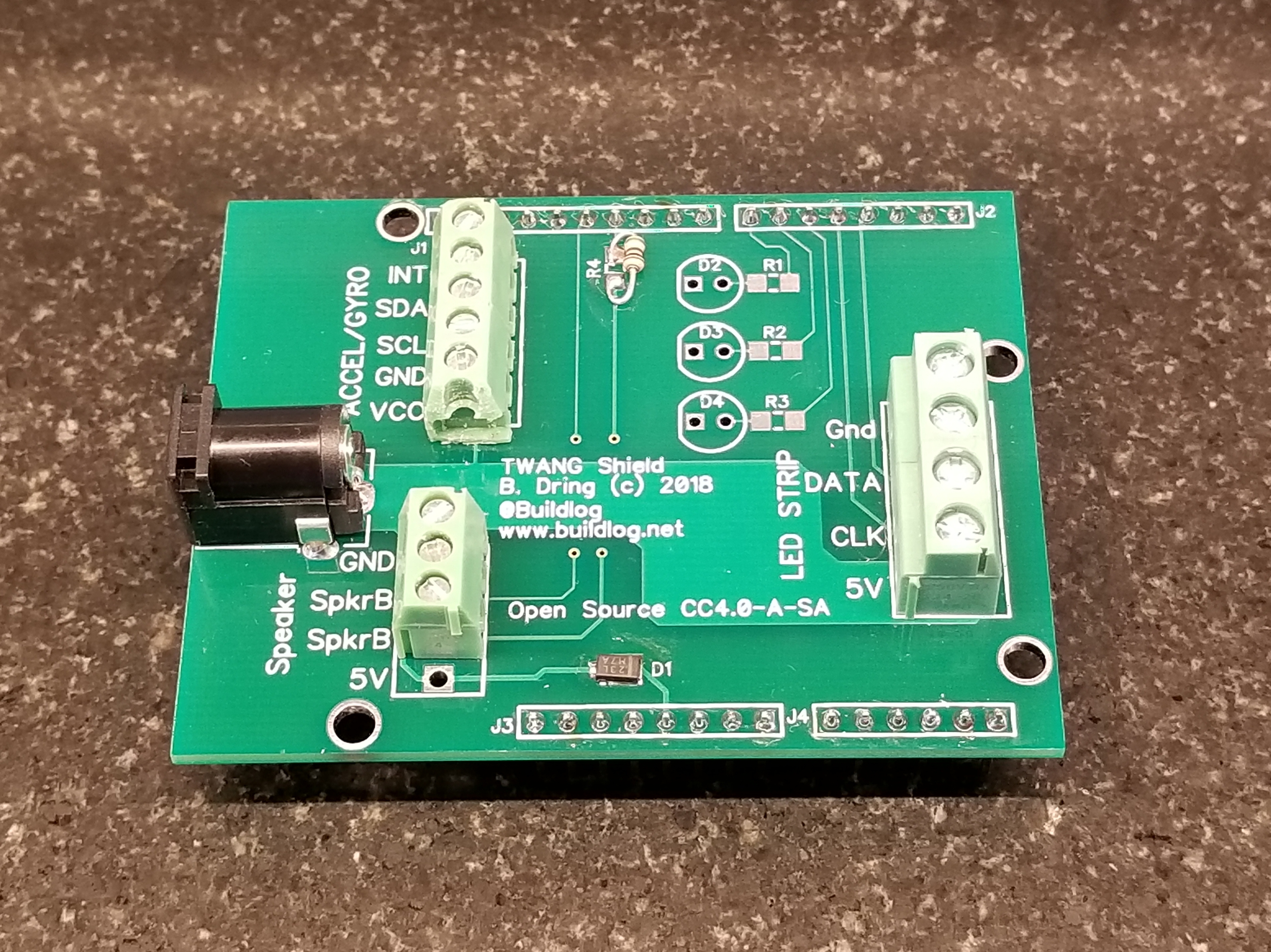
The shield takes care of all of this and groups all of the external connections by function on easy to connect and clearly labeled terminal blocks. Here are the features I have…
- Single 5V Power Connector: This connector powers the LED strip via a very heavy trace on the PCB. It also powers the Arduino. The Arduino is powered through a Schottke diode. If you plug in the USB, the Arduino switches to be powered by the USB. This allows you to program and hack the firmware while the LED strip is powered.
- Terminal Block Connections: The wires are grouped by peripheral (Accel, Speaker, LED Strip) and clearly labeled.
- LED Strip Connections: This powers and controls the LED strip. I have tested it with 4 wire (APA102, Dotstar) and 3 wire (Neopixel) strips.
- Speaker Connection: There is an integral 100 Ohm resistor that is required when you directly power the a speaker from an Arduino. The terminal block also has 5V and Gnd in case you want to add a simple amplifier. BTW: Driving the speaker directly from the Arduino is plenty loud in my opinion.
- Shield Size: The shield will work on both an Arduino Mega sized board or an Arduino UNO sized board. The TWANG firmware requires the extra memory of the Mega, but a tiny, reduced feature, UNO version could probably be made.
- Life LEDs: There are provisions for 3 LEDs that are typically used to show remaining lives. I have not been using those. I prefer to use the LED strip to show remaining lives. I like working with the restriction of a 1D LED strip display.
Prototype Assembly Notes: I did not have all of the correct parts for the build. I did not have a 100 Ohm SMD part, so I tacked on a through hole part. I did not have the right terminal blocks, so I cut one and only used 3 positions for the speaker. The correct parts will arrive soon.
Here are some more images.


Future Changes
- I will probably get rid of the life LEDs.
- I will add a large capacitor for sensitive LEDs, like Neopixels. Right now I just connect the cap to the terminal block.
- I will probably sell the rest of this batch on my Tindie store in a week or two. I will probably sell assembled boards and full assemblies (less LED strip and Mega)
- I will release of the documentation under an CC4.0-A-SA license.
If you want to be notified of future blog posts, please subscribe.


