MPCNC ESP32 Controller Ideas

I have been thinking about designing a custom Grbl_ESP32 controller for the MPCNC (Mostly Printed CNC ) machine. The MPCNC is a simple and low cost CNC machine. The MPCNC is primarily used as a router, but many people often use it for laser cutting and engraving. A custom controller would address the design features of the MPCNC, make it very easy to hook up and the ESP32 would add Wifi, Bluetooth and higher speeds.
The goal would be to create a low cost, open source controller. It would directly address the needs of the MPCNC, but avoid expensive additional add-ons.
MCU

It will use the low cost plug in ESP32 development modules. It will support the 2×19 pin types only, with both 0.9″ wide and 1.00″ wide types supported.
Power Input
I think most people would use 12V, but I’ll size the parts so 24V can also be used. I think a 2 position 5mm terminal block is best. It can handle higher currents than a DC barrel connector.
There will be a small 5V 3A DC-DC power supply on the controller. This will power the MCU when not connected via USB. It will also power a few other things. You will be able to communicate with the MCU via USB power, but most other stuff on the board will not work without the primary 12V power.
Connectivity
- USB: This will use the micro USB connection on the ESP32 module. In this mode you can use just about any gcode sender that supports Grbl
- WiFi: You can stream gcode over Telnet. You can also use the WebUI to control the machine, upload to the SD card, run and monitor jobs.
- Bluetooth Serial: This is a Bluetooth mode that presents itself as a serial port on connected devices. There are a lot of senders that support this.
- SD Card: Running jobs from an SD card is my favorite feature of Grbl_ESP32. When used with the WebUI, you can’t beat it. Also, we may be adding web browser “plugins” that would load pages from the SD card. This could be gcode visualizes and gcode generators.
Stepper Motor Drivers

The MPCNC uses (2) stepper motors each for the X and Y and (1) motor for the Z, for a total of (5) stepper motors. Ganging (2) motors for an axis can be done with (1) driver or (2) drivers. It think it is probably best to use (2) drivers each for the X and Y axes.
I think it is best to use the standard Pololu footprint drivers to simplify things and lower cost, I would hardwire all microstep selection pins to the highest setting. The Grbl_ESP32 can still run crazy fast at high resolutions. I don’t think it is worth supporting drivers with firmware control of current, microstepping and other features. The firmware does not yet support these anyway.
Spindle / Laser Control
I think most people use an AC router for these machines. That means an on board relay is probably the best way to control that. I will also provide a 5v PWM signal on a header connector, for those who want to try controlling the speed.
The laser will also use the PWM for power control. I am worried about people accidentally PWM’ing the relay circuit, so I will use separate I/O pins for the relay and the PWM. That would also allow the relay to be used for other functions when using PWM.
I/O Inputs
- Limit Switches: X, Y and Z limits switches. These can be used as simple homing switches. The firmware also supports putting both max and min limit switches on each axis.
- Control Switches: Feedhold, Cycle Start and Grbl Reset (end job, without position loss).
- Touch Probe: This can be used to zero your bit on the work.
All input pins will have low pass filters on them to improve noise immunity. Optocouplers have been considered, but are probably overkill and technically require an extra, isolated power supply.
Update: In the comments, Drew mentions auto-squaring would be a big improvement for the MPCNC. Is it worth giving up an spare I/O (requires 2 extra pins)
Extra I/O
There will probably be a few extra I/O pins. These will be brought out to a header connector and can be used to add your own features.
Mounting / Enclosure
I am not quite sure about the shape and mounting right now. It will probably be rectangular due to (5) drivers along one edge. I’ll put mounting holes in the corners. I’ll add a connector for a small fan. You probably only need the fan if an enclosure is used. I would love some feedback here.
Question #1: What is more important, small size or detailed, easy to read labeling of the pins?
Probably Not Included
- Local Display (LCD, OLED, etc.): Local displays have been avoided on the Grbl_ESP32 project. The connectivity options eliminate the need for this. A smartphone is a much better interface that allows you to get status, control jobs, upload jobs, act as a pendant, etc.
- Vacuum, Coolant Relays: These are expensive and take up a lot of board space. There are a few extra I/O pins that will be brought out to connector if you want to add these features.
Comments
Please add comments if you think I should change anything or consider some other features.
Update: 3/4/2019
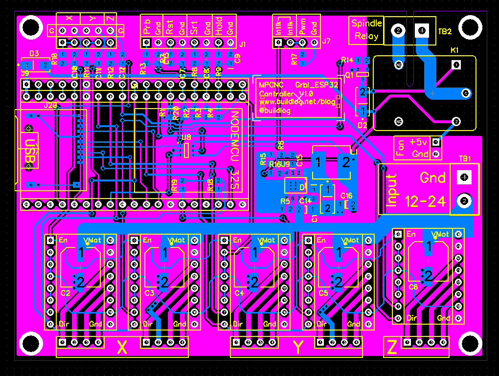
A schematic and layout are now done. I probably wait to order it, so it arrives about the same time I get back from a vacation 3/18/2019.


Bart,
Sounds great. I would use this right now for a board solder paste dispenser.
As for your PWM’ing a relay, you should give some thought here if you have the pins. I’m re-writing your PSoC grbl spindle_control right now for corrected spindle_enable_out control. My PSoC board uses 3 pins for spindle control: enable, direction, speed. spindle_control.c is kind of a mess with all the special condition considerations and legacy 328p code.
Good luck and keep us posted.
Craig
Craig,
I agree.
I think I am going to use a level shifter with an output enable for the 5V PWM. I’ll use the spindle enable for that. That might allow some safety logic in the future and it makes the relay circuit independent from the PWM so it could be used for a new purpose like exhaust fan, vacuum, etc.
Every solution is a bit of a computerize with these little chips. I miss the elegance of the PSoC.
I know it, I’m living in PSoC luxury over here. You may want to consider an I/O expander like MCP23017 for the low speed signals. How’s your flash space holding out, any room for 4th axis? I have other projects where a rotational A on Z is needed (not a pick and place machine).
Thanks the reply.
I have plenty of flash space for things like that. I am trying to avoid an I/O expander for little projects like this.
So awesome…I have 10 of your boards that I got from JLCPCB…got the components in (to build 2)…my kids destroyed my soldering iron..LOL..so waiting for new one in the mail before I try to assemble
There are virtual comm ports that can allow one to create a comm port the native OS that can connect to that port and stream the gcode from native run programs wirelessly to the controller [or upload to SD Card albeit slowly] (it’s how I controlled CNC3018 with an ESP-01 wirelessly…well until I burned out the AMS1117 [just doesn’t have the oomph to drop 18vdc to 5vdc w/o running too hot])
Would be AWESOME to see a custom MPCNC version of your controller!
Hi Bart,
As long as it’s well documented somewhere then you can go small and not worry about the silkscreen too much. If you would rather go the self documentation route then having a larger board is not that big a deal. Please support 24V, I have found the MPCNC works better using 24V (more torque).
A question, does GBRL support work coordinate systems? I have been using linuxcnc and by far the best feature is it’s ability to return to a known zero even after powering down the controller.
Thanks for the feedback
Yes, Grbl supports G54 through G59 as non-volatile work coordinate systems. It should work exactly like LinuxCNC. It also support non-volatile G28 and G30 positions.
I would suggest using two “limit/home” switches and motors on both X and Y. One of the inherent problems with the MPCNC is squaring the X and Y axes to each other. It’s controlled by the central XYZ junction and it’s rather difficult to adjust and keep adjusted. I think you can get by with using 2 home switches on one axis and a single switch on the other axis. Of course this assumes that Grbl can handle homing to two switches on a single axis.
Drew, I did that before as a test using an X-Carve running Grbl.
You need to be able to move each motor by itself. You can use the same switch pin with 2 switches in parallel. For example: The axis moves towards both switches with both motors moving. When it hits a switch, it does not know which switch so both motors back off. It then moves one motor towards a switch and backs off. You then move the other motor until it hits a switch and back it off the same amount. If your switches are square, the machine is square.
The X-Carve only has one axis to deal with. The MPCNC has 2 axes. I think the easiest way to do this would be to give each driver its own step pin.
Can you explain how your “2 home switches on one axis and a single switch on the other axis” method works.
I do have 2 extra I/O pins. I have those brought out to a connector. I thought someone would insist on hacking in a display with those. But, I believe nobody will ever make a DIY display better than a smartphone.
I’m actually looking into building the LowRider2 CNC. looks like the same requirements and I’d love to see a grbl_esp32 controller for it. As long as the board is documented well enough, I think small size is better. Auto-squaring would be great!
Bart, Great way of dealing with squaring the axes! I haven’t tried this but the idea behind the “2 home switched on one axis and a single switch on the other” is that the X andY axes only need to be square to each other so if you consider one of the axis the “master” then you only need to square the other axis to it. I guess there could be problems of the master axis doesn’t always power up in the same relationship to its fixed rails. Any way with your “two switches on the same pin” method you only need a single pin per axis anyhow so each axis can have two switches. Does your version of the ESP23 Grbl support this method of squaring?
Drew, I have squaring for both axes, but either can be disabled and revert to normal homing.
It is not in Grbl_ESP32 yet, but I don’t foresee any issues.