I designed this machine to draw custom, round drink coasters. I already have a laser cutter for square coasters and I wanted to try something unique for round coaster.
The Base
The base of the machine has two stacked 5mm bearings in the center for the bed to rotate on. There are (3) 3mm bearings on the bed perimeter that provide support and keep it level. They have little shafts that snap into the base.
The Bed
The bed is a 156 tooth GT2 pulley. It has little springy fingers that grip the coaster when it is on the bed. The bed connects to the motor pulley with a closed loop belt.
The Radial Arm.
This is a belt driven, cantilevered arm that uses 6mm shafts and linear bearings. The belt is a cut pieces with the ends clamped at the carriage. It has a slotted mounting hole that lets the arm rotate. The pen must be adjustable to get to the exact center of the coaster or the drawing will be distorted. There is a limit switch on the top. This is the only axis that needs to be homed. To setup the machine you home it and jog the pen until it is exactly over the center of the bed. You then set the work zero for X (Gcode: “G10 L20 P0 X0”). This only needs to be done once. If you use different types of pens, the center should be rechecked.
The Z Axis
The Z axis uses a micro servo and a cam to control the height of the pen. The firmware is setup to only have (2) Z positions, pen up and pen down. It uses 3mm rods and tiny little 3mm linear bearings. There is a compression spring on one of the rods that applies a little pressure to the pen, and allows the pen to float a little on uneven coasters.
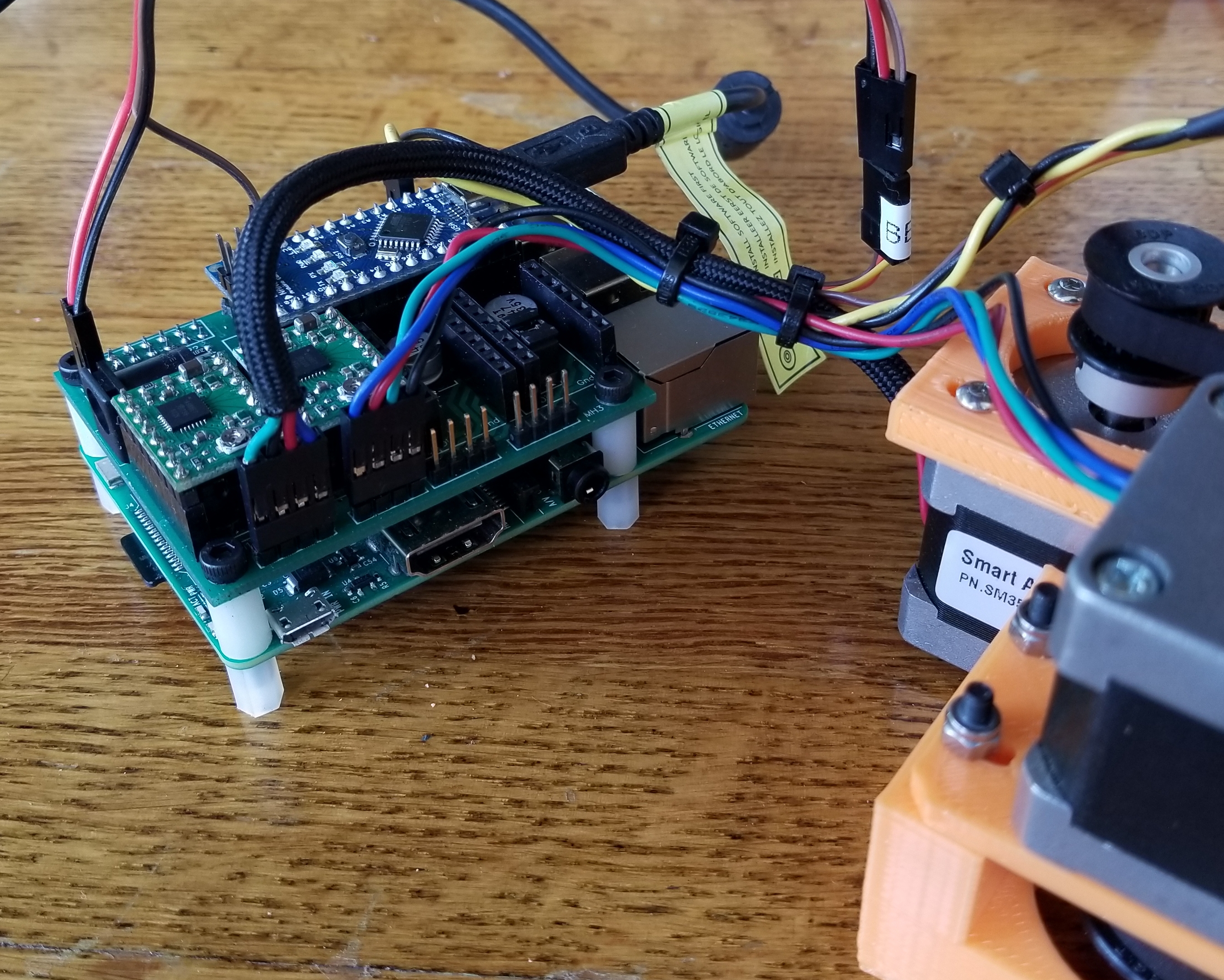
The Controller
I used my Grbl HAT controller. It is a bit overkill for this project but works perfectly. It is attached to a Raspberry Pi in this photo, but I have not been using the Pi in this project yet. I just connect directly via USB.
Kinematics and Pre-Processin
See this blog post on how it was done. The pre-processor is written in C#, but it is rather simple and you could probably read the source file and convert if you cannot deal with C# on Windows.
Firmware
I use a modified version of Grbl 1.1f. Grbl does not support servos, so I needed to hack that in. I used the PWM that is normally used for the spindle speed to control the servo. I turned off the variable speed spindle option and streamlined the spindle functions to the bare minimum I thought Grbl needed. I adjusted the PWM parameters for use with a servo and added pen_up() and pen_down() functions. I tried to put as much of the custom code into one file spindle_control.c. I had to add a few lines in stepper.c to look at the current machine Z height and apply the correct pen up/down function.
CAM
You can use anything to generate the gcode that works with Grbl. The pen will go up when the Z is above zero and down when it is below zero. Therefore, you want the Z movement as short as possible to speed up the drawing and not have the pen dwell on the material and bleed. I make the depth of cut 1mm and the z clearance 3mm.
CAD Files.
The design was done using PTC CREO 3.0. A STEP version of the design is linked at the end of the post.
Performance
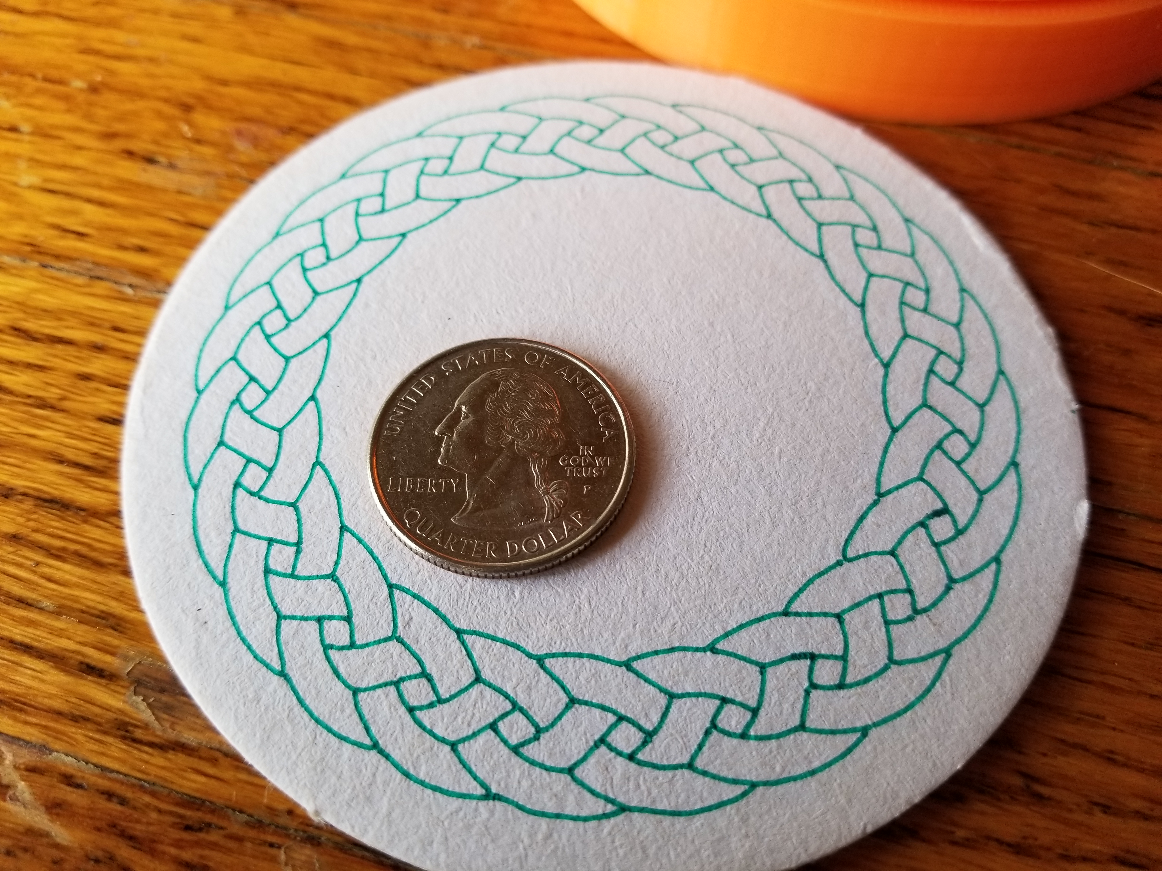
It does a great job. Here a recent coaster. This was done from a rasterized bitmap image found online (searched: circular Celtic braid).
Here is a Fat Tire beer themed coaster.
Coasters are made to be super absorbent, so larger tipped felt pens tend to bleed a little too much. I like to sketch with Micron pens and the thinner ones really work well on this machine.
Build You Own?
The build is not difficult, but covers a lot of areas. You should know how to work with STEP files and compile firmware.
The design is open source with no commercial restrictions, so feel free to use any part of my work. I found most of the parts on Amazon and eBay. I bought the belt from Stock Drive Products. The polar motor pulley is 36 tooth and the arm pulley is 20 tooth. Cutting the shafts requires an abrasive cutoff wheel.
Please post any questions in the comments section and I will try to address them.
When you have a round work piece like a drink coaster, it makes sense to have a round work area. A round work area works best with a polar coordinate system. A polar coordinate system uses an angle and a distance from a center point to define a point in 2D.
The problem is that most drawing and CAM programs work in Cartesian (X,Y,Z) coordinate systems. My machine controller firmware, Grbl, also works in normal linear X,Y, and Z. The process of converting one system to another uses Kinematics.
The Firmware
The firmware is side is actually quite easy. I defined the X axis as the distance in mm from the center (the radius). The Y axis will control the angle. The Y axis is setup so that millimeters will equal degrees. If I tell the Y to move 360mm, it will actually rotate the work area by 360°. I could have used radians, but my brain works a lot slower in radians.
The machine will only need to home on the X axis. It needs to know where the exact center of the work area is. The starting angle does not matter because the coaster is a circle.
The conversion from X, Y to polar is probably won’t fit in into the firmware, so the X, Y conversion is done in a preprocessor software program. The X,Y gcode is output from normal CAM programs, then run through a conversion program.
The Conversion Program
The program reads the X,Y gcode, converts any X or Y coordinates into polar coordinates and outputs a new gcode file. The sender simply sends the new files. The math is actually quite simple.
Typical Gcode sends line data by giving the end points of lines. You simply draw from one point to the next, unfortunately this creates a few problems with a non linear machine.
The basic non-linearity problem
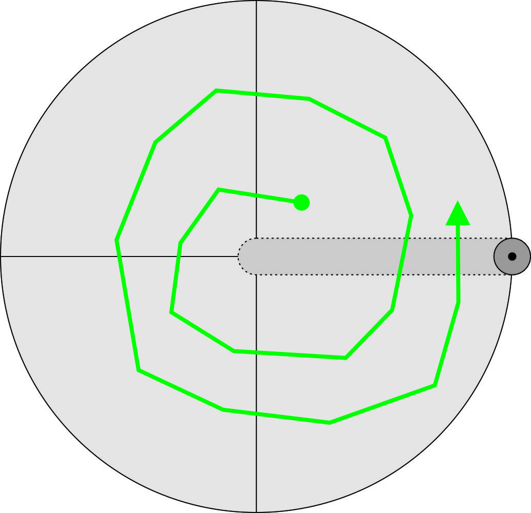
If we were trying to draw the green square centered on the work area, the generated gcode would basically send the corner points. Each corner point has an equal radius to the center. Therefore, the pen will never change radius when going to the next point. This will result in a circle. We want the green square, but we get the red circle.
We need to calculate each point along the way to stay on the desired path. The preprocessor divides the line into tiny segments. Each segment has the same problem, but at a scale you won’t be able to see.
The Spiral Problem
If we are drawing a shape that crosses the 0° angle we don’t want the angle to spin the wrong way. If a point is at 350° and the next point is 10° (crosses over 0) we don’t want it to spin backwards from 350° to 10°. We want it to go to 370°. It happens anywhere the angle difference between 2 points is greater than 180°. The program will choose the shortest direction even if that means going above 360° or below 0° degrees.
The Feed Rate Problem
Feed rate, in CNC terms, is the speed of the tool across the material. The CAM software is setting the feed rate as if this were a Cartesian machine. On this machine, if you were drawing a circle, you would simply move 360 units in Y. Without compensating feed rate, the pen would move across the work piece faster for larger diameter circles. I want to do some sort of compensation to help with this. The coasters are very absorbent, so the lines look thicker if the speed is slower. A consistent speed will help the quality of the work.
Since the lines are all very short, the easiest way to compensate for feed rate is to use the current radius. With a simple circle, Grbl thinks the machine moved 360mm. The real distance is easy to to calculate from the perimeter of that circle.
We can compare it to the 360mm (full circle) and apply the ratio to the desired feed rate from the CAM program.
Here is a video of it. The machine is rerunning a file to see the repeatability.
Next Steps.
I would like to automate the preprocessor. I think a Raspberry pi, might be an easy way to do this. It would sit between the sender and the controller.
Here is a quick update on Coasty. Several people have asked if I am releasing the source files or selling a kit. I am adjusting the design to make that more viable. The original version was made with parts I had laying about and not necessarily the best design choices for an open source project.
X Axis.
Originally I used an TR8-8 ACME thread lead screw. It was mounted to the motor by drilling a hole in the lead screw and epoxying it to the motor shaft. This worked well, but you needed a lathe to drill the hole and a special low backlash nut. The axis was also a little loud with and all metal design.
I changed to use a GT2 open belt cut to length. Belts and pulley are really easy to get and don’t cost too much.
Electronics
Need to shorten some wires after testing.
There were some issues with the EleksMaker electronics that I did not like. The laser circuit did not appear to have a pull down on the signal and it tended to fire if the Arduino was not pulling it low. This would happen during reboot and other scary times. The wiring was also quite a pain. There were no connectors for the limit switches so you had to directly solder to the Arduino Nano.
I changed to use a custom PCB that is the entire rear panel. This contains all of the circuits including the limit switches. Building a Coasty was a little like building a ship in a bottle. Now the bottle has no bottom and there are less parts inside.
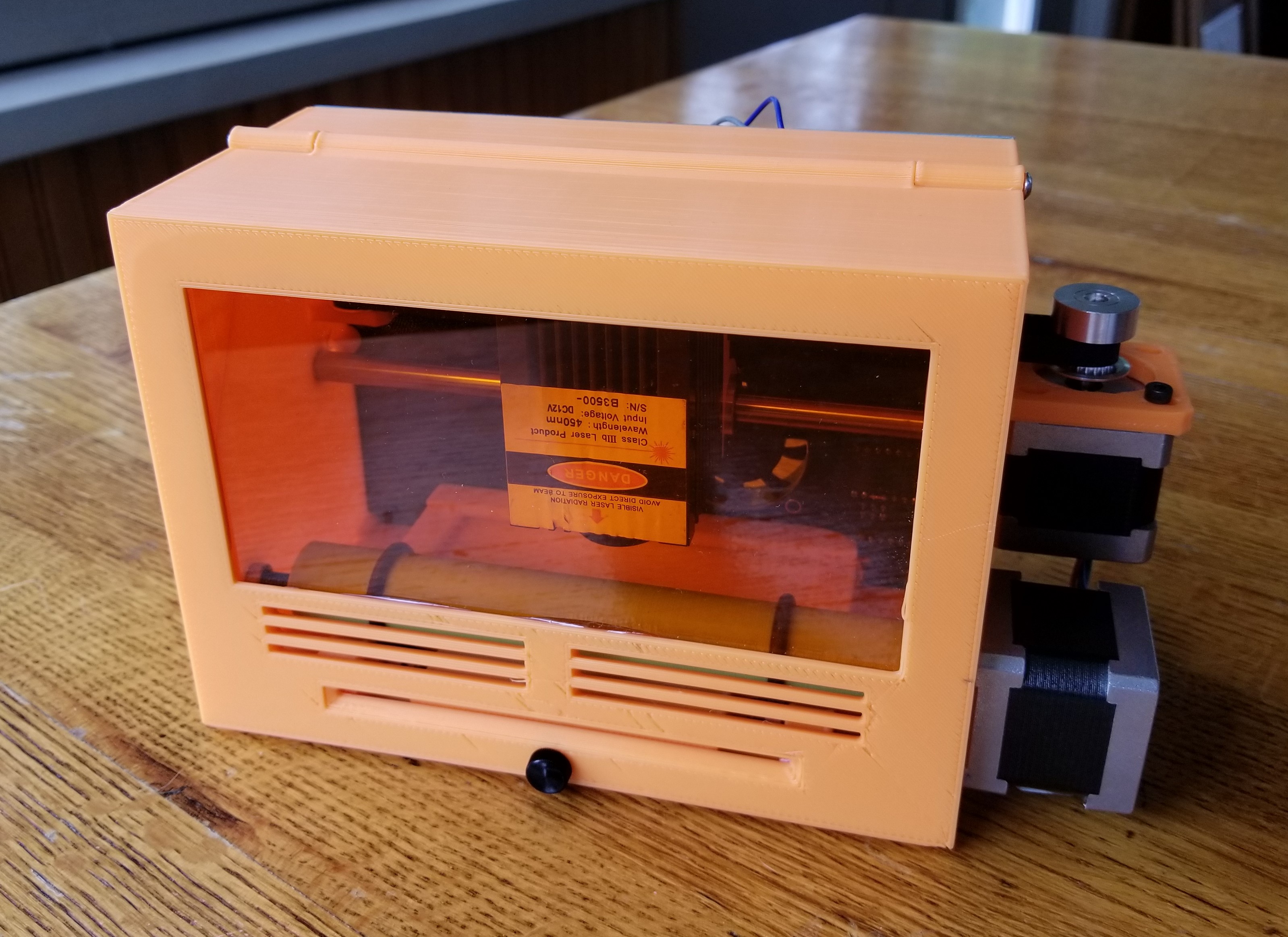
Front Door.
The front door now has a window. This makes the machine more fun to watch and no glasses are required.
Next Steps.
I have one build and am testing it for a while. If all goes well, I will release the source files and consider a kit.
Last week I made a Line-us drawing robot clone. Unfortunately I had no good way to make it draw easily. I thought I would give the CNC toolpath a shot. My goal is to have a super portable thing to generate conversation at meetups. If I used Easel it would allow anyone with a web connection to easily make something.
Grbl
The most compact machine controller is Grbl and I have a lot of experience with it. Grbl is designed to send step and direction signals to stepper motors. The draw ‘bot uses hobby servos. The nice thing about hobby servos is they don’t need to be homed. They have feedback to tell them where they are. They also don’t care about speed, acceleration or steps/mm. They just go wherever you tell them as fast as they can go. It occurred to me, the easiest way to hack this into Grbl was to not modify the Grbl code at all. I would let Grbl think it is using stepper motors. I would just add some extra code that runs on regular interval to tell the hobby servos where the stepper motors are in 3D space and they would be told to go there. I played around with some intervals and 8 times per second (8Hz) seemed to work pretty well. The ‘bot uses machine coordinates. The work coordinates are offset to the left because the ‘bot cannot draw at 0,0. The pen would crash into the frame.
PSoC
I recently port Grbl to PSoC. I used (3) 16bit PWM components to control the hobby servos. See this blog post on how I did that. I then attached a 8Hz clock signal to an interrupt. The interrupt sets a flag when it is time to update the servos. When the main code sees this flag it does the calculations and and sets the PWM values. Keeping the code out of the interrupts gets Grbl happier.
Easel
Easel is already setup to use Grbl. You can either import gcode or create a design right in Easel. I started out with importing gcode because the Benchy design was not in a format I could import. I created a template that shows the allowable work area. This will allow anyone to quickly create a drawing.
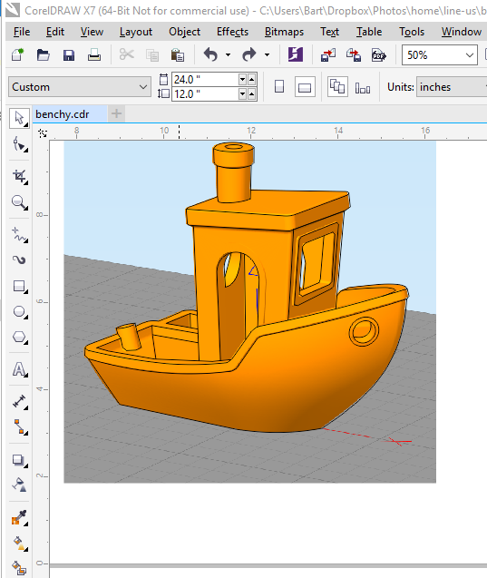
2D Benchy
I wanted to have a little fun with the first print. “Hello World” was not good enough. 3D printers use benchmark prints, so I thought I would do a 2D version of the classic 3DBenchy. To get a 2D drawing of 3DBenchy, I traced over an image with the line tool in CorelDRAW. I then exported a DXF of that.
I have been going to the monthly Amp Hour, Hardware Happy Hour meetup. A lot of people bring something to show. My projects are too big. Also, you need to bring your own power. The meetup standard seems to be running off a USB cord. I was brainstorming ideas, when I saw the Line-us project on Kickstarter. It looked like the perfect size and power. I also love the challenge of non linear kinematics.
I decided to make a clone of it. I started by importing one if their drawings into CorelDRAW and scaling it up to 1:1. I then added some measurements. I rounded them up to 80mm for the pen arm and 30mm and 50mm for the linkages.
I looked into hobby servos and found that the “mini” size looked about right. I ordered 4 of them from Amazon. I made sure to get metal output shafts because I thought I might have to press them into the 3D printed arms.
Design
I created a basic design in PTC CREO. I added a lot of construction sketches for the linkages to help me with the kinematics later. I downloaded a model of the servo from GrabCAD to use while I waited the delivery.
I used 3mm bearings for all the joints. These are pressed into the linkages. This would allow me to firmly tighten the joints and not have to worry about slop in the joints.
Assembly
When the servos arrived, there were slight differences in from the model. The mounting holes we much smaller at about 2mm. I had to reprint with some changes.
My concept was to press the arms onto the servo shafts. This sort of worked, but after a few crashes, they loosened up. I ended up using a drop of thick super glue to secure them. They were able to stall the motor without slipping. It is important to mount the arms at the precise angle. I made an Arduino sketch to hold the servo in the precise position while attaching the arms at the angle I wanted. Each servo has a 180° travel. The upper arm travels from 135° to negative 45°. The lower arm travels from 45° to 225°.
Kinematics
In order make the pen go where you want it to go, you have to figure out what angle to set the arms. This is not a simple linear equation. You have to solve a multi-step geometry problem for each new location. I’ll walk you through the basic process. I placed the axis of the two servos at XY 0,0 to simplify things. You know the desired Pen Tip location, so start working back towards the cranks.
Step1: Find the Pen A point. You know the lengths of the linkages between the 0,0 point and the pen tip. They are both 50mm. Each arm end has a set of points where it can exist that scribes a circle. If the desired pen point is within reach of the machine, the circles (green ones) will cross at two points. The solution is a well documented process. I used the C code from this page. So far, I found that using the location, of the two, with a higher Y value is the one to use.
Step 2: Find the Pen B point. Pen B is easy to find because you now know the slope of the Pen Arm. Multiply the X distance from the pen tip to the Pen A point by the ratio of the length of the pen arm (80mm) over the length of the arm from Pen Tip to Pen A (50mm) and add it to the pen tip. Do the same for the Y axis.
Step 3: Now that you know the Pen B location, you can do the intersecting circles (red ones) trick again. This time I used the left most point of the two.
Step 4: Find the angles. Use the X and Y distances of the crank tips and the atan function to get the angles. ( angle = atan(deltaY / deltaX) )
Another problem with non linear machines is that moving between two points will not be a straight line. The points will typically be connected with a slightly curved line. You need to constantly recalculate points along the way to keep it straight. If you break a line into smaller segments, the connecting curves also get smaller to the point where they are not notices.
Electronics.
Everything I chose was for prototyping ease and probably not the final solution. I used an Arduino UNO as the controller. I used a PCA9685 based servo motor controller for the servo. The Arduino could probably handle it on its own, but the wiring is so clean and simple with this. I used a breadboard power supply to power the servos. It had a handy switch to kill the power to the servos without killing the Arduino.
The Results
Here is a video of the machine running. The rectangle is hard coded via some for loops recalculating at 1mm increments. The results are shaky, but consistent with the Line-us results. The machine is quite rigid. Most of the shakiness comes from the servo motion. I also do not have the machine held down. If I get some magnets like Line-us, it might help.
Open Source (sorry)
I don’t think it is fair to the Line-us folks to release any files at this time. I think there are plenty of resources in this blog post if you want to clone it yourself. So far I only have about 5-6 hours into the project, so it is pretty a pretty easy project.
The real Line-us looks very polished and they are selling it at a good price. I am sure a lot of the work they did was on the UI, which I did not replicate at all.
Next Steps
I need a way to stream drawing data to the machine. I would like to use g-code. It also needs a UI and I thought Easel might be best. For the gcode I might try hacking Grbl. I would just add a timer that reads the current location at about 5hz, send it through the math and set the servos. Any value above Z 0 would be pen up.
For Easel, I could create a template that shows the usable work area. You would then just click Carve.
Firmware
Here is the firmware I used. It is a quick and dirty port of my PSoC port of Grbl. I cannot give support for this. Only experienced PSoC programmers will be able to install and use this.
Here is my STEP file of the design. This contains all of the printed parts and some of the hardware. You will need to figure out a few things on your own.
It’s ORD Camp time again this weekend. Every year I have done a gonzo build of some type of CNC machine. This year I only had a few hours to spare, so I wanted something simple. These are never meant to be practical machines, just conversation starters.
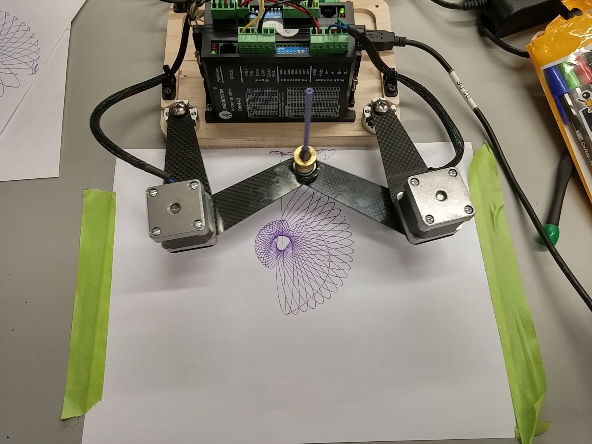
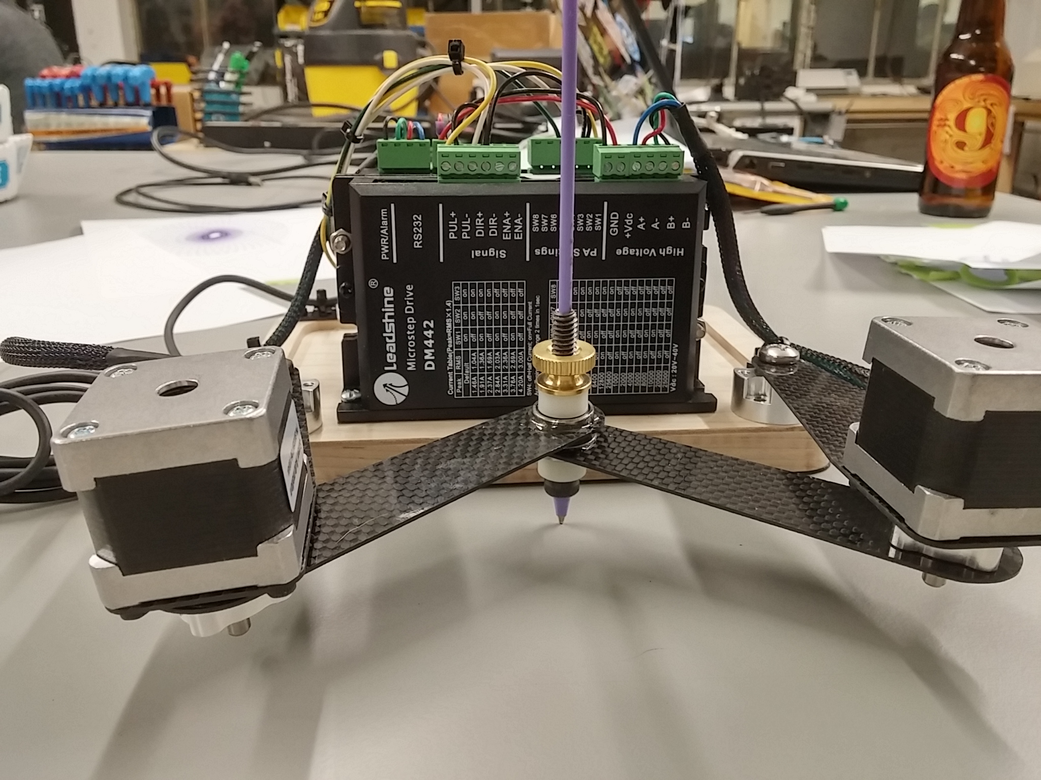
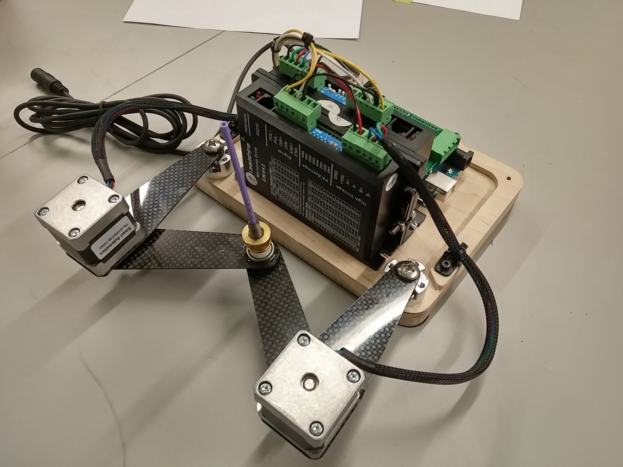
This was hacked together and programmed in about two evenings with stuff I had laying around, but working at Inventables means there is a lot of cool stuff “laying around”. It was inspired by the RepRap Wally 3D printer, but vastly simpler in construction. This only uses a couple of fabricated parts. There are (2) sets of indentical actuator arms. The inner arms are hard mounted to small NEMA 14 stepper motors. The other end is attached to a wood base, but free to rotate on a bearing. The outer arms are mounted to the stepper motor shafts using Actobotics hubs. The other ends have 1/4″ I.D. flange bearings. These are bolted together, but free to rotate using a screw with a holed drilled for the pen. That is basically it for the mechanics.
The stepper motors are driven with some high resolution stepper drivers. These are driven by stock grbl 0.9 firmware running on an Arduino UNO. The UNO does not know what the heck it is driving though. The resolution is done in degrees. I wrote a quick conversion tool that converts Cartesian gcode to bipolar gcode using these formula.
L = 150mm
A = 90mm
I have my CAM software output circles as multiple lines, so circles don’t need to be dealt with. It has an odd, shield, shaped work area that you need to stay within. Before powering on the steppers, you place the pen at the top middle of the work area. You then tell grbl that both angles are at 51 degrees with G92 X51 Y51.
Here are a few more pictures taken at this weeks Beer and Making session at Inventables.
The shield has a solenoid driver that I was going to use for pen up, but I never got around to that. I kind of like how it runs so silently.
Here is a video of it running. It is rerunning over an old plot to show the repeatability. I think if I used true inverse kinematics the plots would look even better. Maybe Machine Kit on a Beagle Bone is in its future.
UPDATE:
A few people have asked if the motors could be moved to different locations. Yes, I think you could put the (2) motors on any (2) joints and still have a controllable machine. Not all work areas would be the same size and some might have issues with much higher torque requirements. I believe separating the the motors by one linkage, like this one, yields the best results.
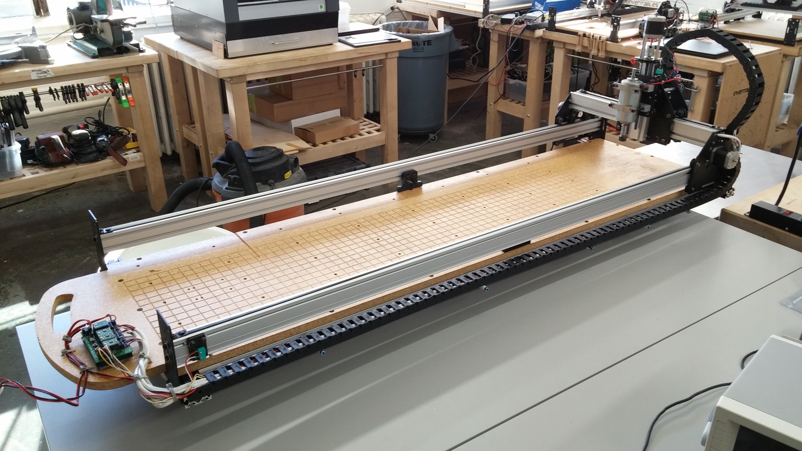
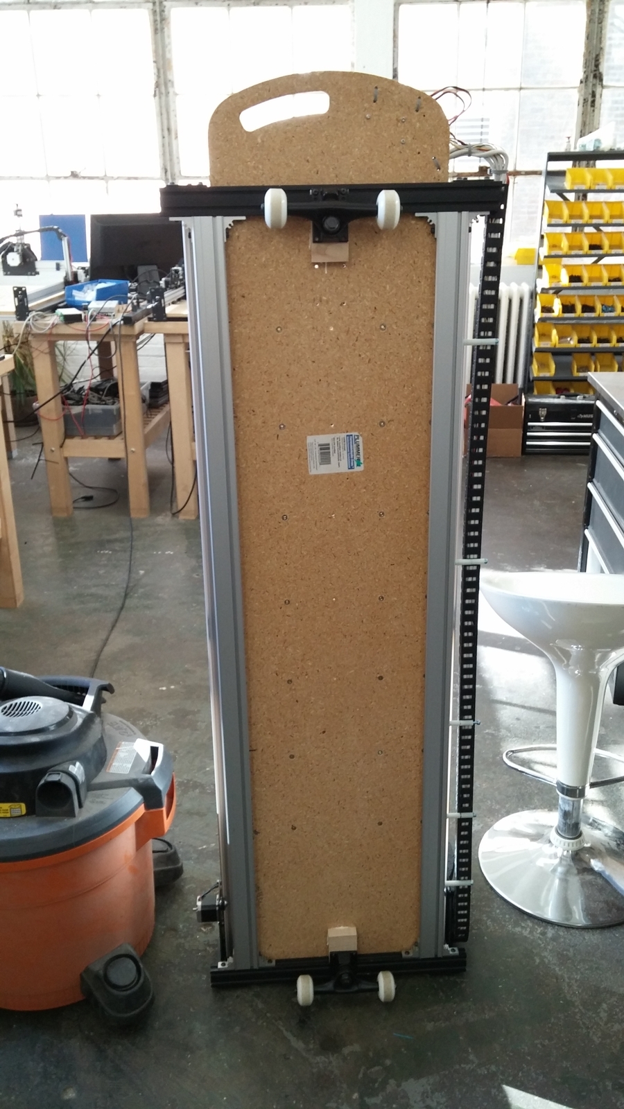
We build a lot of skateboards for fun at Inventables. Some of the guys even sell them at local craft fairs. They thought it would be cool to have a CNC router optimized for skateboards that was easily portable. I first thought about putting wheels at one end, then realized the machine itself could be a skateboard. We thought it would make a perfect Gonzo Build.
A Gonzo Build is something we came up with at Pumping Station OneCNC Build club. The concept is that we try to build an original, “one off”, CNC machine in one evening. They also tend to have a whimsical aspect to them, so we don’t take ourselves too seriously. We usually get about 8-12 people to help build. If parts need to be fabricated, they must be done that night on -site.
Building a stock Shapeoko 2 in one night is a challenge in itself, but we decided to up the challenge by totally tricking this out with every feature we could think of. We did have a few master CNC building ringers in the group, like Tait Leswing and David Ditzler.
Here are the stats of the machine.
1200mm x 250mm work area
Skateboard specific wasteboard supported by additional extrusions. It is narrower than a stock Shapeoko 2 and about 3 times as long.
Portable dual 24V/48V power supplies with master power switch.
Most of the Shapeoko parts came from reject area at Inventables, so there are a few dings and scratches.
The wasteboard was cut from 5/8″ particle board on the PS1 Shobot. It has a grid v carved into the work area. There are threaded inserts for clamps, primarily around the perimeter, but there is a truck bolt pattern strategically placed so a cut out board can be flipped or remounted accurately . It is supported below by 2 additional MakerSlide pieces and tied to the MakerSlide rails above. It is the bed turned out very rigid. It does deflect a little with heavy rider but pops right back. After the build, I added several coats of spar varnish to ward off the dusty footprints. Biggest guy to ride it so far tips in at about 230lbs.
We set our selves a goal of completing before midnight. Done or not, I was going to ride it at midnight. We thought we were finished about 20 minutes early. Everything worked fine except the Z axis was not moving correctly. It had the classic stutter and random motion of one coil wire not connected. We tried to find the problem, but over 2 meters of drag chain slowed us down. Midnight came some we dropped it to the floor and I rode it across the shop.
As a skateboard, it is pretty much a joke. On the first ride, we didn’t even have long board trucks, so the turning radius was huge and you can easily scrap an edge. The front has a handle cut into the nose of the bed. The ideal way to move it around is to lift the front and drag it on the back wheels.
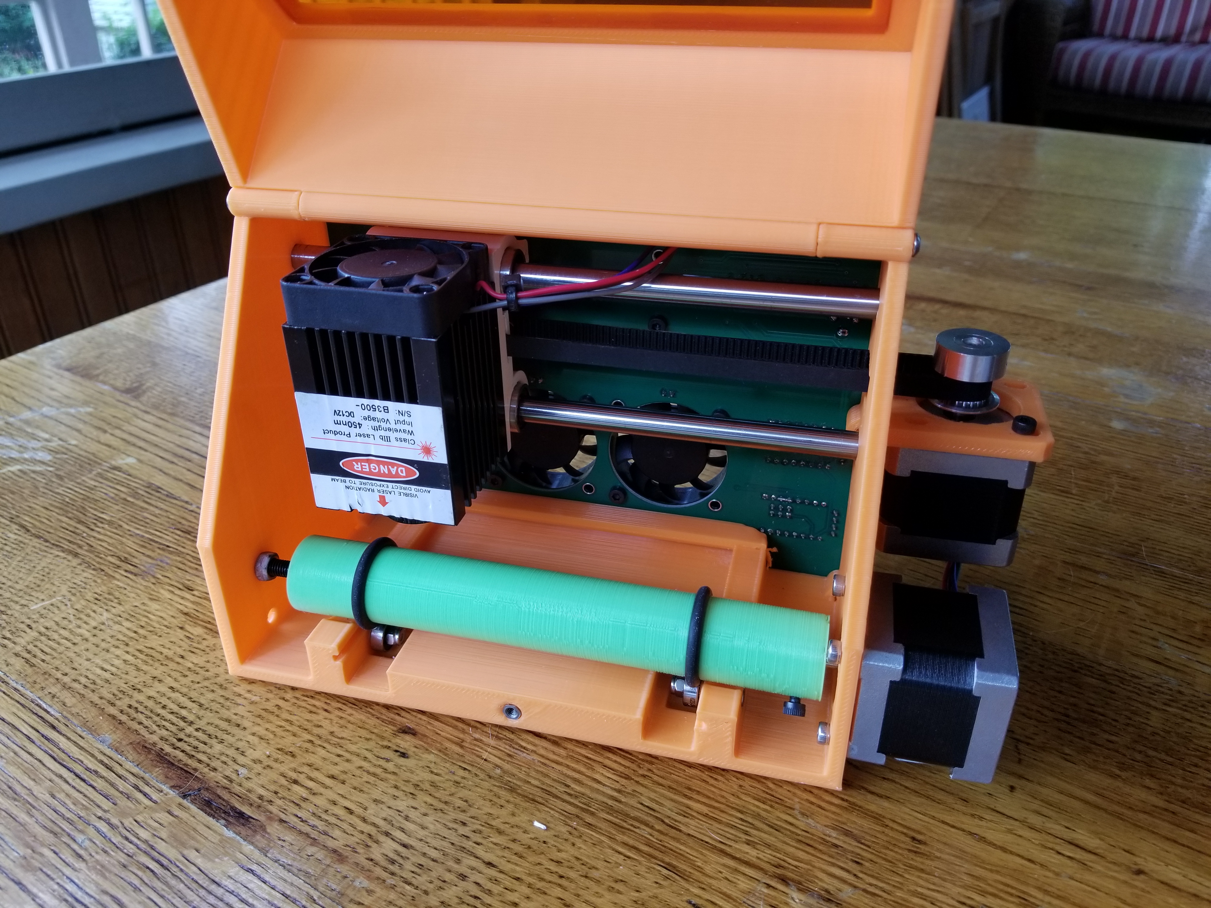
When our Hackerspace, Pumping Station One, had it’s mini router repossessed by a member who was leaving, I decided to design a replacement. As always, I wanted to try out some new ideas on the build. I also wanted a project made primarily in metal to force me to get up to speed on using my CNC Bridgeport. The result is Bridgie.
Bridgie?
Bridgie was inspired by the Bridgeport’s sliding X axis, so the working name became Bridgie. The other inspiration came from a sliding chop saw. This was used on the Y axis. The Y axis is remarkably stiff and makes the Z far stiffer than many other routers I have used.. All rods except for the Z are 20mm hardened steel and the 12mm ball screws add strength. The X is even stronger and the bearings always stay directly under the spindle. The entire machine weighs about 45 lbs..
Clean Design
I wanted a very clean design, so I designed it so it is totally self contained. The power supply, controller, limit switches and motors are totally contained inside the body of the machine. The only external interfaces are power and USB on the back. There is also a fan on the back that blows directly on the motor drivers and flushes any hot air out of the interior.
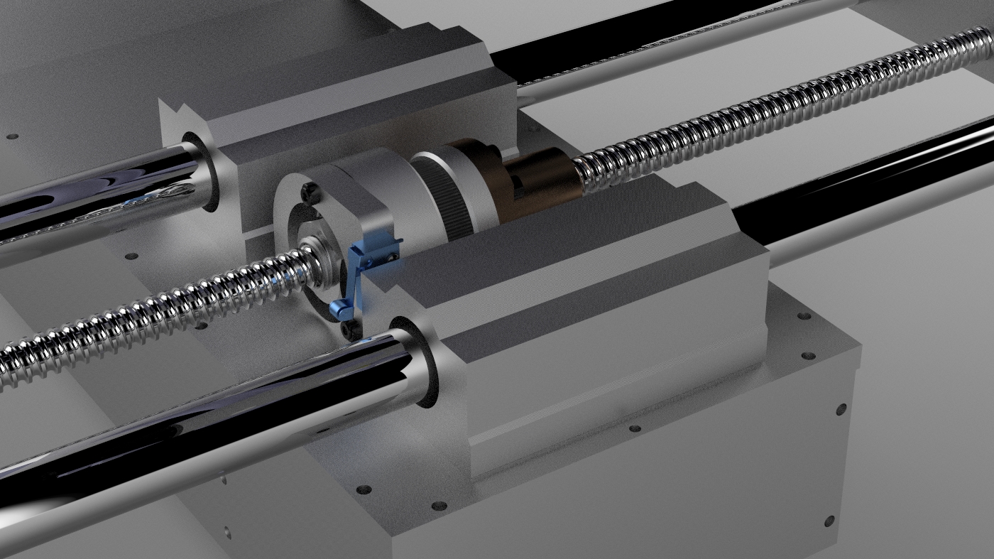
Spinning Ball Nuts
It uses 12mm ball screws on the X and Y axes. In order to bring the motors inside, I decided to use spinning nuts and stationary lead screws. This actually simplifies things because you don’t need to put expensive bearings on the lead screw, you just firmly attach it to the end plates. The lead screw becomes a structural member in the machine. The bearing on the nut is important for reducing backlash, so I used a large dual angular contact bearing. These were about $10 each from VXB. I did not take too many pictures during assembly, so here are some screenshots and renderings of the design.
Exploded view of the nut assembly.
Top view of X axis nut area
Bottom view of X axis
Controller and Firmware
The controller is an Azteeg X3 with a Viki LCD. I have used the X3 on a lot of projects. It worked really well on this project because it has the on board SD card and works well with the Viki LCD. The firmware is a highly hacked version of Marlin. Here is what I changed.
Totally altered the LCD menu system to be right for a router.
Tore out all the temperature stuff.
Left in the extruder features in case I want to add a rotary axis. I have used the extruder as a 4th axis successfully on other projects.
Added a Z zero touch plate feature.
Added a G54 machine offset like feature in EEPROM. You you set a 0,0,0 for your workpiece, you can recall this later if there was a power failure or other crash.
The arrow keys on the Viki jog the machine. In jog mode the up and down keys jog in XY. The rotary encoder is still active and sets the rate of the jog, so you can jog XY in fast, slow and micro mode all from one screen. Z can be jogged as well on it’s own screen.
There is a feedrate override feature on the main screen to speed up or slow down the feedrate.
All features are accessible via gcode, so pendant use is not required.
Homing and Work Offsets
The machine can be homed at any time. The Z homes first at the top of travel before homing the X and Y so this is less likely a chance to hit a clamp. Homing at the top of Z is not too useful for setting up your job, but the machine will now know the limits of travel and will never crash into the ends of travel.
The machine then homes at minimum X and Y. There are also two other configured locations called “park” and “access bit”. Park moves to center X, zero Y and top of Z. The head is out of the way in this spot so it is easy to clamp the work piece in this location. It is also has the minimum footprint in this mode for easy transport. It also has an access bit location that moves the spindle to the front for easy access to change the bit.
You can jog and set a work 0,0,0 anywhere you want. The machine resets it’s soft limits so jogging or G Code cannot crash at either end of any axis. If you restart the machine, you can recall the last work 0,0,0 so a previous job can be completed accurately.
Feature List
Work area 12″ x 8″ x 3.5″
T Slot table (larger on all sides than the work area for clamping).
Sliding X table – Like a Bridgeport.
Spinning lead screw nuts.
Jogging with the pendant arrow keys
Z touch plate. You can manual set the Z zero on the top of the workpiece or it can be done automatically with a touchplate.
X,Y,Z limit switches.
Park feature that moves the machine into it’s smallest size for transport.
Weight: heavy…about 45lbs
Soft limits. If you set a new work zero, the machine still knows the new limits of travel.
Does not need a PC. It can run completely off the SD card with control via the pendant.
No exposed wiring.
Super quiet DC spindle.
Cooling Fan directed on drivers, but flushes the whole interior.
“Park” command shrinks the size to smallest footprint to help with transport.
Freaking heavy at over 45lbs
Videos
To Do
It would be nice to have easy access the the SD card. It is buried inside the unit now and you need to upload files to it via USB.
Add a real feed hold (immediate deceleration like grbl does now)
Changes.
There a few thing I would do to make it a little easier to fabricate. A few holes were difficult to drill and tap and some simple changes would make that a lot easier.
I added an e-stop button since taking these pictures that cuts the DC power.
I wrote a couple post processor files for the Southwest Industries TRAK AGE3 CNC controller for my Bridgeport mill. The post processors should work for all Vectric programs, like Cut2D, V Carve Pro and Aspire. My Z driver has an problem, so I am currently working in AGE2 (2 axis) mode and these were written for that mode. There is an inch and a metric version of the post processor.
The files are output with a .CAM file name. They need to be saved with a numeric filename, so they can be read by the controller. Once imported, they are editable like standard hand input AGE programs. I think AGE is limited to 2000 events. You could have the post processor limit it to that many lines, but I did not do that yet.
Warning: Test this with air cuts and a hand near the e-stop.
Every year I make a new thing for ORD Camp. This year I made a delta router. The ORD contraptions I make, have one primary function; to spark conversation. This means they have to be interesting, a little whimsical and a little cool looking. They are generally rather small for portability and to keep the costs down. Practicality and suitability are way down the list, so go ahead and snark away. If you do, you are missing the point.
This year there happened to be a session on creativity with constraints. The question we debated for an hour was, do constraints help or hurt the creative process. Constraints can move you out of your comfort zone and maybe that is a big part of creativity. The topic was perfect for me because I had intentionally challenged myself with a few constraints on this project.
Use non captive stepper motors. Not a lot of people have seen these in use, they are cool to watch and they simplify the design.
Limit myself to 3 unique fabicated parts. People keep thinking deltas are more complicated than . This was to demonstrate the simplicity. Go ahead, design a Cartesian machine with only 3 unique fabricated parts. All other parts had to be commonly available parts.
Use stock reprap software. I could only touch the configuration files.
Design
I met all the constraints except for one. I designed a common top and bottom bulkhead, but at machining time I decided it was silly to to spend the time to add holes only used on the top to the bottom and the same with the top. So the four unique fabricated parts are the top, the bottom, the carriages and the end effector. The top and bottom are 3/4 inch Baltic birch. The other fabricated parts are 3mm carbon fiber. All parts were setup and cut in less than 30 minutes on my homemade CNC router. A 3D STEP of my design is here.
Mechanicals
The vertical rails are MakerSlide. I used steel V wheels because I had them laying around. The rest of the mechanical parts are Actobotics parts from Servo City. I thought they were an awesome discovery and then the next day I saw that Sparkfun started to sell them. They really worked out great. My only complaint is that they are imperial thread based parts. I prefer all metric on my designs.
The non captive stepper motors are really cool. The thread is a 2 start 8mm trapoidal, so it moves 4mm per rev. They are quite fast and strong. I custom ordered them at Robot Digg. The only drawback is you cannot move them by hand. You can’t spin the rod or the motor. In this design they are a little vulnerable too. If they get banged hard they could bend.
I used some mini arcade style switches for the limit switches. They are pretty nice snap acting switches, but probably a little less accurate than microswitches. I chose them because they would be super simple to mount without adding mounting brackets.
The controller is my favorite reprap controller; the Azteeg X3.
Spindle
The spindle is a brushless DC hobby motor. It is a Turnigy Trackstar. The speed controller is a Turnigy Plush 30. The shaft is 1/8″. I used a simple shaft coupler to mount the bit. This added a lot of vibration so the motor could not run at full speed, but that was OK becuase the full speed is close to 30,000 RPM and 550Watts!. I eventually manually balanced the coupler and it runs a lot smoother now. I did it by drilling through the existing set screw holes to the other side with a small bit. I enlarged that hole until it was balanced.
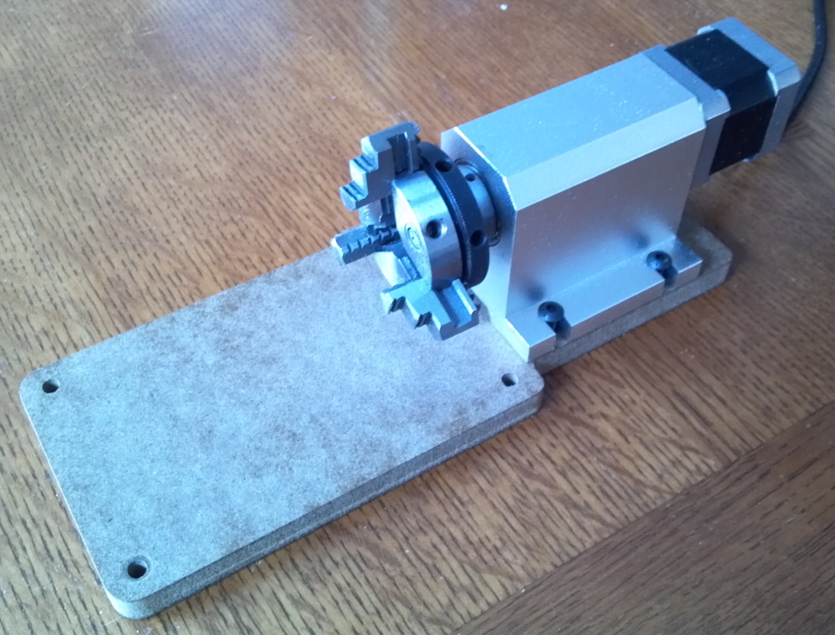
4th Axis
Later when I got home, I thought it would be cool to add a rotary axis to it. The challenge was going to be using the extruder motor logic for the rotary axis. I had this attachment laying around that was bought from eBay a few months ago. A typical 4 axis machine simply disables one of the axes while using the rotary. That is not possible with a delta, so all 4 axes need to run at the same time. It is quite fun to watch.
It was perfect because it was so small. It has a 6:1 reduction gear inside. I made a simple base for it that would allow it to be quickly mounted to the router.
Firmware Changes.
The firmware changes to Repetier were pretty simple. Extruders use millimeters as the feed unit, so I just converted that to degrees. The motor is 200 steps/rev with 16x microstepping plus 6: 1 gear reduction. This yielded 53.333 steps per degree. I changed the safe extruding temperature to a very low value and then just wired a 100k resistor across the thermistor pins so it read a constant value above the safe temperature.
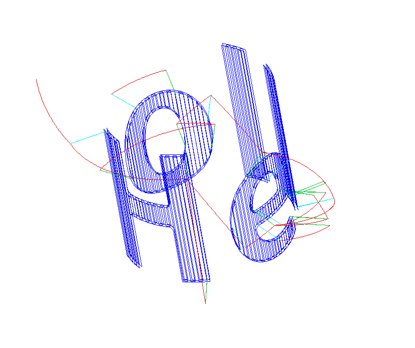
CAM Software
I don’t have any high end CAM software that does anything really cool on a rotary. I did have an evaluation copy of DeskProto, but that timed out. I did have Vectric V Carve that does have a wrapped rotary feature. That would be good enough to do my Hello World project. I had to write a post processor for it. I basically hacked the Mach3 wrapped rotary post processor. I had to make it really simple and tell it convert “A” moves to “E” moves. There were a couple other changes too. The post processor is here.
Changes and Issues
I really need a tail stock to support the stock and help set up the job level.
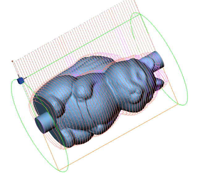
The feed rate on rotary axes are tricky because millimeters per minute is quite different than degrees per minute and there is no way to deal with that in GCode. The actual feed rate through the material depends on the radius (Z). Programs like Mach3 can compensate for it. I could really hack the firmware or maybe write a post post processor to compensate the speed based on the Z.
I need to get some real software to some interesting carving with this thing.