Buildlog Title: Flickerfly's ORD Bot Hadron Build Log
Builder: flickerfly
Member Since: 2013-04-27
Sunday, April 6th 2014 - 4:20 PM
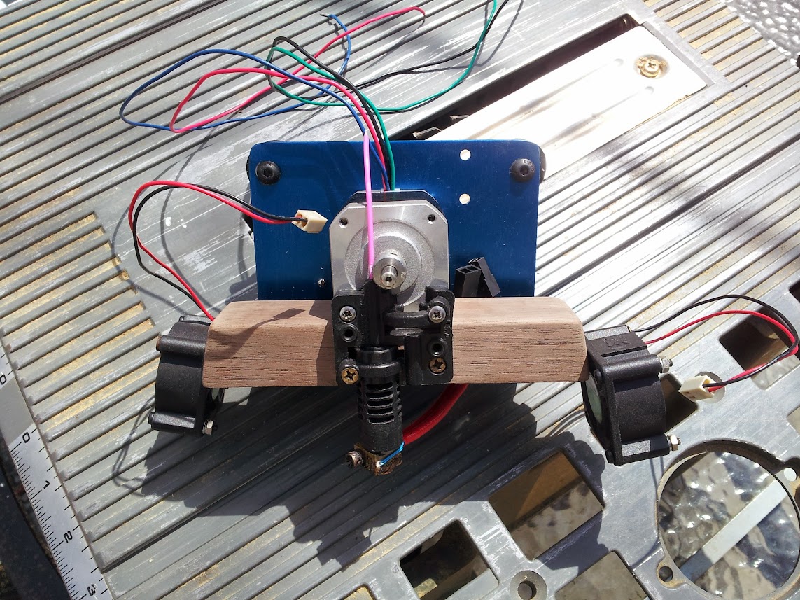
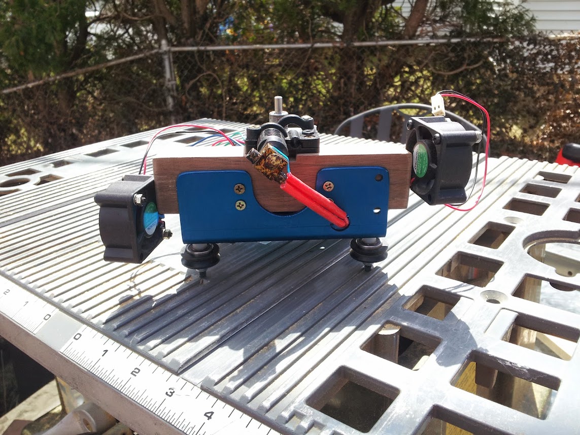
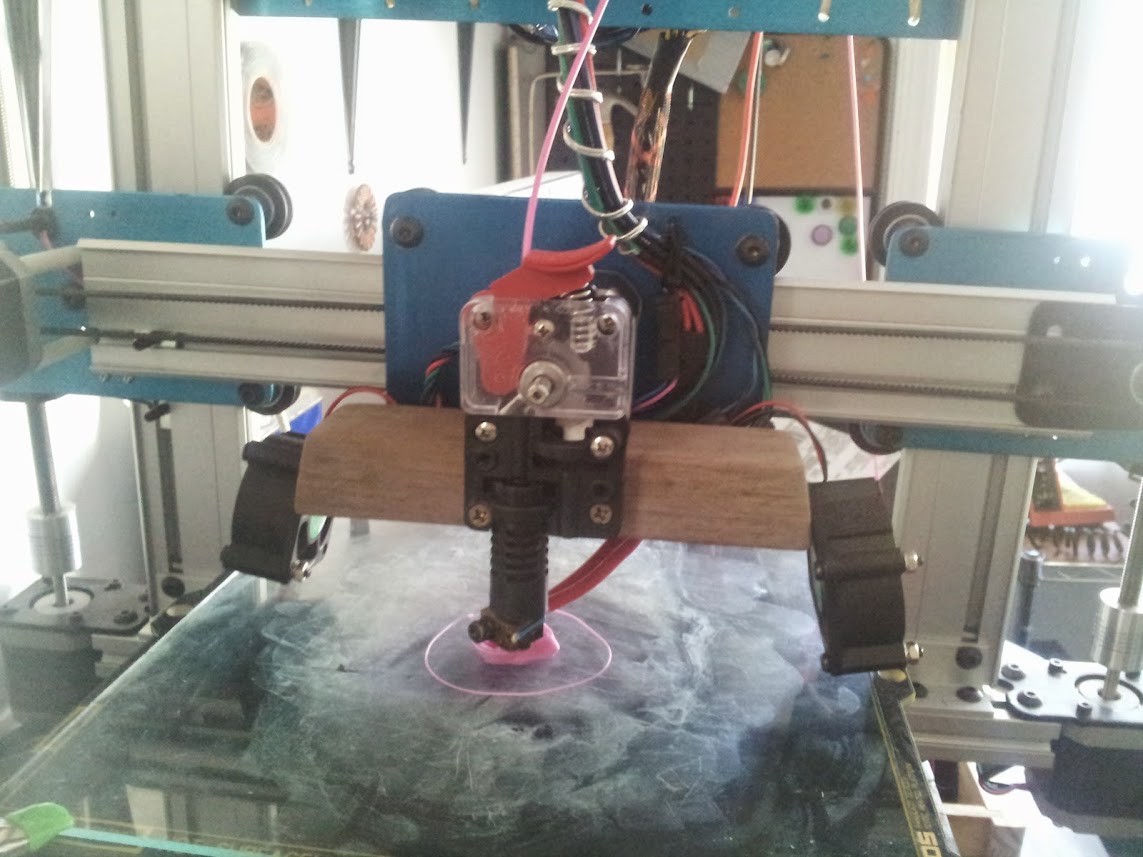
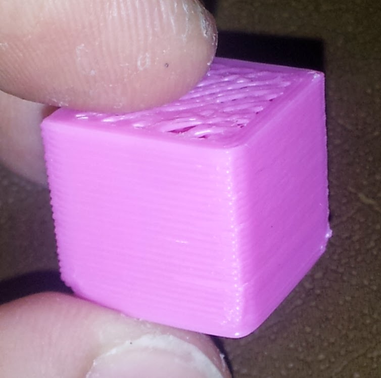
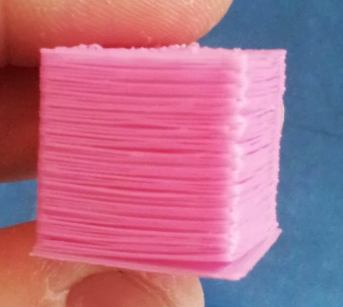
My last attempt at extruder mounting took me backwards. The new mount used a weaker mount and smaller stepper. With the direct drive EZstruder, it just wouldn't keep up. I found a nice peace of beautiful hardwood scrap and rebuilt my mount again now with fan mounts on bot sides. Now my printer is doing better than ever on the first 15mm calibration block. I'm super pleased. The cooling certainly has a big part of it, but the bigger stepper for the direct drive extruder is also helpful and I wonder if the mount being across the entire shelf add a certain amount of stability to it.
This one also makes room for a dual extruded setup in the future, maybe even three extruders.
Here's a few shots of the new mount made entirely on the table saw.
I need to work a bit on my heatedbed temperature. I also have some wiggle in my X and Y still, just a bit. I think I'll be printing a couple new mounts soon to deal with that.
A few more tweaks to get a few more things working right. It should be noted that I have it setup to turn itself off after a certain number of seconds of inactivity. This works with mechanical endstops with the Y homed to MAX and the X and Z homed to min, but using the MAX pins. Attachements...
I've recently upgraded my Repetier Firmware to 0.91. Attached is the configuration.h for folks who are interested in putting together a similar bot. Attachements...
I finally got my FT231x on the Azteeg X3 replaced. I burnt that chip and was limited to basic serial communication. In the mean time, I rewired the printer running all the cables on the inside of the extrusion that I could. I also mounted the X3 high enough off the back plate to allow me to solder in connectors on the back and run my endstop and stepper lines under the board cleaning up the look a great deal. For that I used the Molex KK series and in conecting the other end of the steppers I used some mini-fit connectors.
I also found Elmer's school glue sticks work much better than the blue painter's tape for my purposese on ABS. I've also started messing with PLA, but that seems to be more touchy about bed leveling so I'm getting a lot of curled up corners with the PLA I'm using.
I had found that the way I configured my Y axis with the endstop had flipped my Y axis so the Y position 0 was actually Y position 200. Once I told the robot to home to Max and had the proper max pin set, it seems to be no longer doing any mirror image printing. I think these are my final settings for the axis at this point. I also attached the whole Configuration.h since I'm sure I've tweaked a few other things I'm forgetting.
#ifdef AZTEEG_X3
#define SDSUPPORT false //turning this off due to an error it causes in compiling see: http://code.google.com/p/sdfatlib/issues/detail?id=39
#define SDCARDDETECTINVERTED false
#define SDCARDDETECT -1
#define FAN_PIN           17  // Originally 4, but changed to use expansion board
#define FAN2_PIN          16  // Originall 5, but changed to use expansion board
#define LIGHT_PIN         6
#define BEEPER_PIN        33  // Activate beeper
#define BEEPER_TYPE        1

// I have my min and max pins reversed on the Azteeg X and Z axis so that I could add a connector to my endstops on the back, where I could easily solder the connectors on without desoldering. I don't use the max, just the mins so this provides that option and keeps my cabling clean.
#define X_MIN_PIN          2
#define X_MAX_PIN          3
#define Y_MIN_PIN          14
#define Y_MAX_PIN          15
#define Z_MIN_PIN          19
#define Z_MAX_PIN          18
#endif
Oh yeah, one more thing. I've wired up the ATX power supplies power on pin so I can turn on and off the 12V from firmware. I then set the firmware to automatically turn off the power supply when idle the same way it does the steppers by setting #define MAX_INACTIVE_TIME 1200L. Then I commented out #define ENABLE_POWER_ON_STARTUP so that it wouldn't turn the power back on after each reset and in slic3r's printer settings I added M80 ; make sure the 12V power is on to the top of the Start G-Code window to tell it to power on before it tries to move or heat up. I honestly turn that all on manually while I'm getting a print sliced so it may not be strictly required. I like the reduced noise of the power supply when I'm not using it and the energy savings are nice too in case I ever need to get this thing Energy Star rated.
You've made it this far so... the not quite completely cleaned up wiring looks like this.
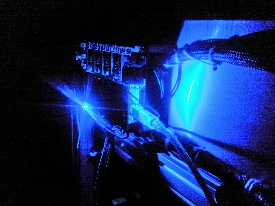
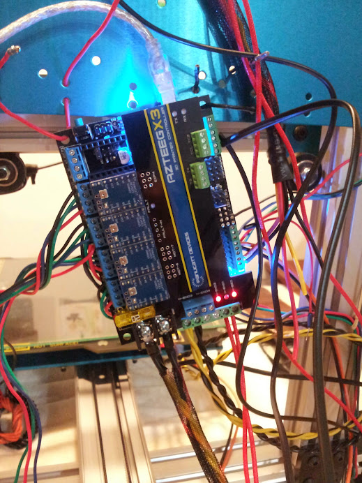
and the Azteeg X3 in the dark is a dramatic presence
These belt clamps that came with the ATI kit are clearly not cutting it. I'm getting the belt sliding in them again. I tried printing some new ones, but the belt slide seems to be impacting that. I should have don that first thing last time I fixed it.
Anyway, do you guys have any recommendations or mods for improved belt clamps?
Today's lesson is that if the EZStruder gets put on backwards and you try to use the 3mm side for the 1.75mm plastic, it will likely cause the plastic to jam. Don't do that and you'll avoid awkward jams after two layers. Looking back, I can see my last picture shows it backwards.
Also, if you blow yout your FTDI on the Azteeg X3, it is possible to rig up an FTDI Friend (that's what mine from Adafruit is called) to the J2 header and communicate via that instead. Sometimes I have to pull the FTDI friend off the X3 and put it back on after connecting to get it to respond to commands, but it does work. I'll try to replace the FTDI chip later.
Here is that wired up:
I soldered some right-angle KK connectors to the bottom of the board so I can mount the wires under the board and make it pretty in the final construction.
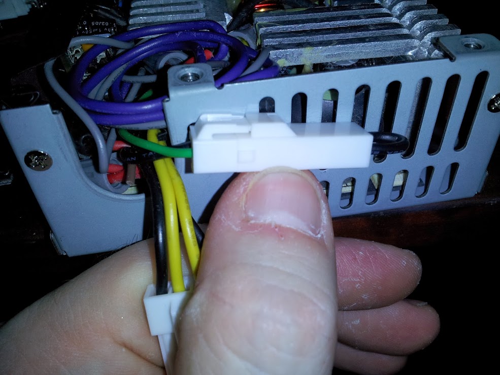
I added a connector to my power supply to allow me to eventually run a wire up to the X3 to have the Arduino turn the 12V on and off as needed. For now I just have a jumper on it.
I also made the first print of my X3 mount adaptor. I think I'll need to lower or remove the wire tie mounts entirely since I soldered the connectors on the bottom. Also, I did this on Make Lehigh Valley's reprap which seems to have some belt slippage and I didn't level the bed so it isn't quite right. I may also have the Arduino Mega hole flipped on one or both axis. I haven't figured that out quite yet.
Looks like a released the magic smoke in my FTDI chip on the Azteeg X3. I'd just changed over to USB power and put the daughter board on while the board was powered. Apparently, that is a very bad idea. I guess I need to go find my external FTDI board and do some soldering.
Thanks, I was looking for that in Slic3r, but couldn't find it. I did find the slowing down, but I think once it hits the top, it really should have more options as you mentioned. Know where it is?
I was also considering some ducting to distribute the air flow. I printed out the starship cooler on thingiverse, but it doesn't work at all on my setup and I don't see an easy way to modify it. I'm dreaming up some other options. Maybe it's time to start a slicer comparison thread to see why people pick what they pick.
Comment from: cvoinescu on Monday, October 14th 2013 - 12:52 PM
It may help to turn on the Orbit feature (that's what's called in Skeinforge), which increases the time it takes to print the very small layers, enough for the plastic to solidify properly. It is even more effective with a fan, because the hot end "orbits" around the print while waiting. The alternative, slowing down on small layers, doesn't work nearly as well, in my experience. With the hot end right there, covering the layer almost completely, the plastic doesn't cool enough, fan or no fan.
Monday, October 14th 2013 - 12:34 PM
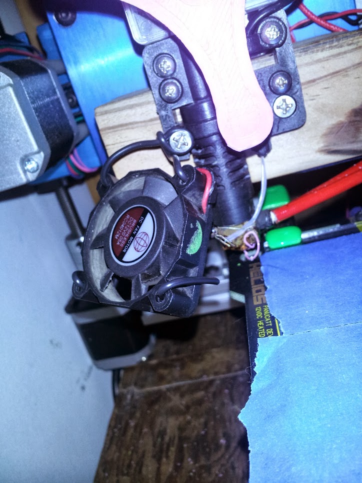
Wow, what a difference a fan makes in printing ABS. I still have some issues with the top of this very small print. I may just get a fan that moves more air.
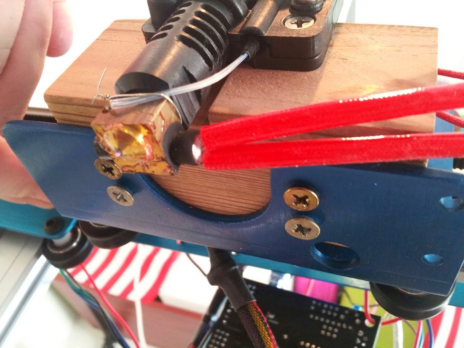
Here is an image of how I mounted the 40mm muffin fan to the EZ-Struder, at least for now. It's a simple bit of heavy gauge solid wire wrapped around a screw and through the mounting holes on the fan.
Here is a before and after pic of the print job.
In order to get this far working, I plugged it into the Azteeg's H-END3 on the expansion board and edited pins.h on the Repetier-Firmware to set pin 17 (the pins on the wiring diagram for H-END4 and H-END3 are reversed). Here is how lines 418 through 427 currently appear. In order for these to take effect, I had to make sure I was using #define MOTHERBOARD 34 in the configuration.h
#ifdef AZTEEG_X3
#define SDSUPPORT false //turning this off due to an error it causes in compiling see: http://code.google.com/p/sdfatlib/issues/detail?id=39
#define SDCARDDETECTINVERTED false
#define SDCARDDETECT -1
#define FAN_PIN           17  // Originally 4, but changed to use expansion board
#define FAN2_PIN          16  // Originall 5, but changed to use expansion board
#define LIGHT_PIN         6
#define BEEPER_PIN        33  // Activate beeper on extension shield
#define BEEPER_TYPE        1
#endif
Note: I haven't yet heard the beeper or light pins or looked into if these settings are correct. They are simply the defaults.
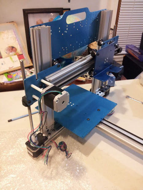
So the Z-axis hangup seems to have been resolved in me widening the space between the upright extrusions which were causing the wheels to have a dent in them. Also, I found that the material I wedged into the belt clamps to secure them didn't work as well as I thought and was indeed allowing the belts to slip. It worked initially which is why I had ruled that out, but when I finally gulped my pride and went back over my work I found that error on both the belt mounts. I put in a different material that I don't think will compress to resolve that. It's good for now, but I'll watch it. Mechanically, I think I'm all set. I'm now playing in OpenSCAD to build a mount for the X3 that has extra space under it to run wire.
I've attached it as it actually is complete, but I'm trying to add a new feature which I can use to pass zipties through.
Comments on possible improvements are welcome! Also, feel free to steal the modules for the X3 and ArduinoMega standoffs for your own purposes.
// Based on Thing #14742: http://www.thingiverse.com/thing:14742 // By Josiah Ritchie <josiah@josiahritchie.com> // For mounting a Panucatt X3 controller in holes for an Arduino Mega/RAMPS // includes extra
// Some basic settings standoff_inner_radius = 1.75; // How big a hole should be in the middle of the standoff? standoff_wall_thickness = 3; // How thick should the walls of the radius be? height_x3 = 15; // How tall should the X3 standoffs be? height_am = 3; // How tall should the Arduino Mega standoffs be?
translate([0,inner_radius,-outer_radius])rotate(a=[0,90,90]) { difference() { cube(size = [outer_radius+(outer_radius/2),outer_radius*2,outer_radius], center = true, $fn=20); cube(size = [inner_radius+(outer_radius/2),inner_radius*2,inner_radius*2], center = true, $fn=20); } }
}
// Make a basic standoff module standoff(height,thickness,inner_radius) {
// Inner radius + wall thickness = outer radius of the standoff outer_radius = inner_radius + thickness;
// Make the standoff cylinder and remove the hole in the center difference() { cylinder(h=height,r1=outer_radius,r2=outer_radius,$fn=20); cylinder(h=height,r1=inner_radius,r2=inner_radius,$fn=20); } }
// Make 4 standoffs and space them appropriately for an Arduino Mega module arduino_mega_standoffs(up,out,in) { // Arduino Mega mounting holes are at [0,0],[81.5,0],[1,48],[75,48] bl = [0,0,0]; //bottomleft br = [81.5,0,0]; //bottomright tl = [1,48,0]; //topleft tr = [75,48,0]; //topright
// Support structure to connect posts for Arduino $fn=100; linear_extrude(height=1.3)barbell([tr[0],tr[1]],[tl[0],tl[1]],6,6,230,230); linear_extrude(height=1.3)barbell([br[0],br[1]],[bl[0],bl[1]],6,6,240,240); }
// make 4 standoffs and space them appropriately for a Panucatt X3 module x3_standoffs(up,out,in){ bl = [0,0,0]; //bottomleft br = [101.6,0,0]; //bottomright tl = [0,64.3,0]; //topleft tr = [101.6,64.3,0]; //topright
// X3 holes are in a square 4"x2.53" (101.6mm x 64.3mm) on center standoff(up,out,in); translate(br)standoff(up,out,in); translate(tr)standoff(up,out,in); translate(tl)standoff(up,out,in);
// Support structure to connect posts $fn=100; linear_extrude(height=1.3)barbell([bl[0],bl[1]],[br[0],br[1]],6,6,2000,230); linear_extrude(height=1.3)barbell([tl[0],tl[1]],[tr[0],tr[1]],6,6,240,1500); linear_extrude(height=1.3)barbell([br[0],br[1]],[tr[0],tr[1]],6,6,150,150); linear_extrude(height=1.3)barbell([tl[0],tl[1]],[bl[0],bl[1]],6,6,150,150); }
Thanks. I've been contemplating taking it all apart, drilling holes for the wire, giving the v-wheels a closer look and that sort of thing. I'll look for some time to do that and get a bit more familiar with my printer.
Comment from: cvoinescu on Thursday, August 1st 2013 - 3:50 PM
Loose belts, loose V-wheels and loose pulleys can all explain the non-round circles. That's probably also what causes the infill not to touch the perimeter, if that's what you mean by "holes". It could also be loose screws -- pretty much anything that moves but shouldn't.
As for your gantry, it's plenty heavy to slide down on its own, so the fact that it doesn't is worrying. Check the V-wheels. They should roll smoothly, and they should be tight but not too tight. As a guide, you should be able to force a V-wheel to turn against the stationary rail with your fingers, but it shouldn't be easy to do so. At any rate, there shouldn't be any wiggle room, but the gantry should move smoothly and without too much resistance. Make sure the V-wheels and the rail are clean -- even a small speck of dirt can interfere with smooth movement.
I haven't yet figured out why the circles aren't round. I can't figure out if I should blame hardware or software and I'm also not sure why I'm getting those holes in the prints. I should probably set aside time to focus a bit more on just one problem, but I think I need to get my wiring cleaned up first so that nest of potential issues is out of the way.
Ah, the belts! Yep, I took another crack at tightening the X-Axis and the calibration thing I'm printing looks much more round.
Thank you!
I have some other issues, but I just carried it back and forth from the hackerspace. I think that may be bed level issues.
Edit: I spoke too soon, as this is printing more it is showing it's not so rounded-ness. It might be a bit better though. I'll have to print something I printed before to be sure.
Comment from: orcinus on Thursday, July 11th 2013 - 10:22 PM
If your infill and perimeter don't connect only on one side or one axis, and the axes move the correct number of mm when you issue a G command (and it's not a matter of steppers skipping), then it's likely backlash. Sounds weird, but it'll sometimes pop up in, say, circles, but not in squares for some reason (current theory - the changes in speed over a circle's X and Y function exacerbate it).
Check your belts, tighten them if not tight, and more importantly, check your belt clamps. You can have a tight belt and loose clamp, causing backlash despite a taut belt. Also check the pulleys just in case (are they centered, are they eccentric, are the set screws tightened).
Comment from: TLHarrell on Thursday, July 11th 2013 - 10:10 PM
I'm not an expert, but maybe take a look at your acceleration and jerk settings for the circles. And for the infill not connecting, perhaps your calibration for flow is off? I'd make the assumption that there's not quite enough plastic spreading out to make the proper connection.
Thursday, July 11th 2013 - 2:18 AM
I'm back from vacationing and recovering from vacation and stuff. Now to get this thing doing circles...
I'm really stumped on this making round circles thing. I checked my X and Y calculations and confirmed that when I tell this thing to move 10mm in either axis it indeed does. I wonder if it is related to why the walls of my prints aren't always aligned with my infill. There is a gap sometimes as seen in this picture. Does anyone have any thoughts on this?
I also printed out the ord bot logo in its not so round state and a handle for my new filament box built with my Dad from my grandfather's home cut lumber using trees from his grandfather's land (which is still in the family). My daughter helped us build it. I love the story and history in that box!
I've been meaning to build a spool holder container for my filament. I have some plexiglass that may be a good start. maybe I can just fill the bottom with rice too.
Right now it is just a dowel across a couple boxes. What sort of humidity causes problems like this? I don't think of the room it is in as generally high in humidity.
Comment from: kbob on Tuesday, June 25th 2013 - 6:45 PM
flickerfly wrote:Thanks Orcinus, it's interesting that you'd see it consistently like that. I'll go ahead and lower the extruder temperature a bit and see if things change.
You can also try storing your filament in dessicant to remove any moisture.
Tuesday, June 25th 2013 - 3:09 PM
Thanks Orcinus, it's interesting that you'd see it consistently like that. I'll go ahead and lower the extruder temperature a bit and see if things change.
Comment from: orcinus on Tuesday, June 25th 2013 - 1:48 PM
I've had similar issues caused by outgassing from the filament, yeah.
And no, it doesn't have to be irregular. The "bubbling" that i've seen was very regular in straight sections. If the filament was soaked consistently, the steam will build up periodically.
Worth trying another filament / lowering the temps so you can eliminate outgassing as the cause.
Tuesday, June 25th 2013 - 1:26 AM
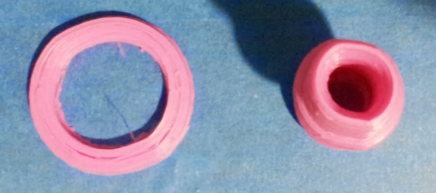
I thought I'd figured out that my little holes were retraction, but that doesn't seem to be the case. Now I'm realizing that I'm hearing popping sounds in my prints and thinking I may be getting moisture or I'm just heating it up too high during extrusion, The heating and moisture don't really ring true though due to the consistency of the holes. Wouldn't that be inconsistent, yet I can print the same thing on two different days and it will result in the same holes in the same or nearly the same places. This includes running slicer on it two different times.
The "pimples" in this were from me trying to fix the holes using retraction, but just causing more problems. The holes remain and are consistent despite retraction settings as seen in these two prints.
I'm wondering if the circle issue is related to the holes since I seem to see them more on round parts and the round parts are stretching on the X axis so maybe pulling the plastic. Here's the view from above on some round prints.
I'll keep studying, but if you have some experience that suggests what I'm seeing, I'll gladly take it.
I have the default slic3r 3-layer perimeter and the infill was .4 or more on every layer. Also, it was messed up before the rest of the head printed so I don't think it was a support issue. It actually browned the plastic on the back so I'm wondering if there is some sort of heat issue, but it only happened where it skipped between the tail and neck so I had a bit of ooze. Am I running to hot and burning the plastic when it sits in the nozzle rather than running through it?
Edit: As I was looking more closely, I noticed lower on the neck across from the tail that there was actually a line up the head where the plastic was missing. Thinking back, I've also noticed little holes like that in other parts and maybe one per layers so I was wondering if the retraction was overly aggressive and reduced it. Moving it to .75 actually caused what I've seen called "pimples" in other areas of the parts. Seems retraction was not the issue.
Another problems I need to look into is the poor quality of my round parts. They have clear stretches to the back left and front right.
Comment from: rickmellor on Sunday, June 23rd 2013 - 5:19 AM
What are you using for minimum perimeters and infill? Is it possible that the walls are too thin so on the steep angles there's not enough support for the outer perimeters?
Sunday, June 23rd 2013 - 2:20 AM
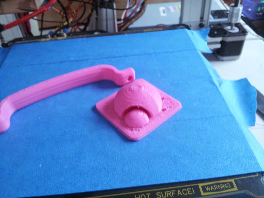
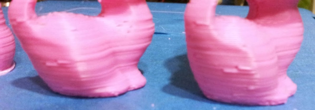
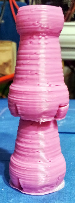
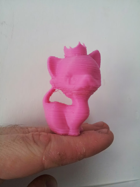
My daughter turned 7 thursday, but her enthusiasm for the Ord Bot Hadron has not suffered as a result. She made a special request for a Chess Set. I'm not sure where she picked up that idea, but we toured Thingiverse until we found a fun kitty themed chess set that she wanted to try and sat in my lap for as long as I'd let her watching it print. Below is the results.
The one thing I noticed was that the oozing was a problem, as seen in the tail and the layers in the neck corresponding to the tail. I assume that is all ooze related. Any advice on dealing with that better? I'd like to fix that before I print out the rest of the pieces.
Comment from: flurin on Tuesday, June 18th 2013 - 8:52 PM
flickerfly wrote:I also tried flurin's hair band for my daughter. I have had some trouble getting the ends to stick to the bed. His shows some sort of square anchor, but slic3r isn't doing that for me. It is pushing the boundaries of my printer a bit so turns out to be good for my education.
In Slic3r Setting>Print settings>Skirt and brim you can set a brim (eg. 4mm), however this will surround the entire object (it's added to the first horizontal shell).
Tuesday, June 18th 2013 - 2:58 AM
I finally spent some quality time with the uprights and have much better results. Z-wobble is now largely mitigated and Z-ribbing also. Now I'm playing with temps for the various parts and slicer settings. This image shows the improvement. It also shows some, what I believe is, over-heating of the bed causing the layers to collapse.
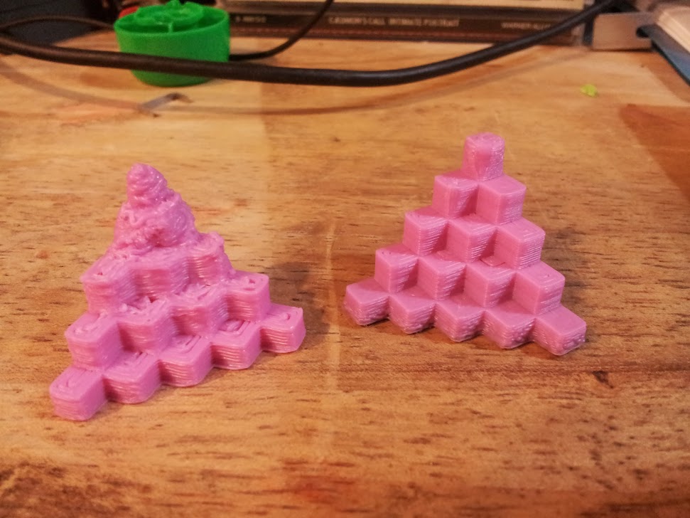
I went a bit more adventurous and tried a 1/2 sized version of myself that turned out better than I expected. The green one a friend printed months ago and is there for reference.
I also tried flurin's hair band for my daughter. I have had some trouble getting the ends to stick to the bed. His shows some sort of square anchor, but slic3r isn't doing that for me. It is pushing the boundaries of my printer a bit so turns out to be good for my education.
Comment from: orcinus on Wednesday, June 12th 2013 - 11:15 PM
Having the temp tables accurate isn't a requirement for successful prints. In fact, you can be 10 degrees off and it still wouldn't matter.
Each filament is different anyways (even batches from the same filament maker can vary a lot) and you need to go through a few meters testing at different temps until you find a sweet spot.
FWIW, i never calibrated mine - i've been using the stock EPCOS 100k tables since day one, despite not using an actual EPCOS. For a long time, i didn't even bother calibrating the hotend PID values.
It's not the accuracy that's important, it's keeping the temperature stable and finding the sweet spot for your particular filament (and print type).
Comment from: rickmellor on Wednesday, June 12th 2013 - 10:50 PM
Do you have a way to verify the hotend temps? I have a multimeter with an external thermocouple that I use to verify. It's important that you confirm this because the temp readings are subject to positional errors. Most people dial it in manually over time, but just checking it is faster.
Wednesday, June 12th 2013 - 6:48 PM
I gave those ZAXIS_STEPS_PER_MM = 2519.68504 settings a try with a .4 layer height. It does appear to improved some larger inconsistency that was on top of the finer inconsistency. Perhaps I was dealing with both and now I have one less problem. Thank you!
Also, I changed the skirt and the flare at the bottom was made smaller so that solves that and I know I don't have to worry about it. We're slowly making improvements so that's good.
That was an interesting article. I'll try the settings you shared next time I get some time to sit in front of my printer. I'm rather excited about this development. Thanks for sharing.
Comment from: rickmellor on Wednesday, June 12th 2013 - 1:57 AM
I'm not sure this is Z wobble so much as Z ribbing. The constrained Z axis with the maker slide makes Z wobble nigh-impossible (assuming your eccentric spacers are tightened correctly). Have you read this article: http://goo.gl/ci9Gz ?
We have the same Hadron kit from ATI from the same batch and we both have X3's... I have mine set for 16x microstepping (not required, but doesn't hurt). My ZAXIS_STEPS_PER_MM is 2519.68504 (I calculated it then confirmed with a dial indicator). I've only tried printing at .2mm and .4mm so far. For these layer heights I calculated the step-corrected height as .1984375mm for the .2mm target and I just multiply by two for .4mm height (.396875). When I get around to refining further I'll probably get better numbers than this, but at least they should fall closer to step boundaries and avoid the errors that result in ribbing.
If you're still stuck on this you might give this a shot and see how it works for you. My build isn't having any issues like this... mine are more to do with temperature calibration. I spent all day Sunday creating new thermistor tables for my build.
Here's my second or third print. You can see that I don't have the Z issues ... the specs throughout are from temp being too high, as well as the mid back.
-Rick
Comment from: Gadroc on Wednesday, June 12th 2013 - 12:56 AM
Rick is correct in that's what I was referring to. Ironically I think the z wobble is better on mine after switching back to the original attached nut block.
Tuesday, June 11th 2013 - 11:10 PM
Oh, yeah. I was thinking I want to do that also more flexible z-stop. It just hadn't drifted up my priority list. It would be much better than the frustration of setting it now which is very time consuming. Thanks for clarifying rickmellor.
It'll allow you to precisely set your Z stop to prevent dragging the head across the bed.
Comment from: rickmellor on Tuesday, June 11th 2013 - 10:58 PM
Not sure if related, but the Hadron I recently assembled came from ATI and I had to get a replacement for one of the Z rods. The threads were damaged and would not mate to the Z nuts.
Tuesday, June 11th 2013 - 2:24 PM
Gadroc, did you have an ATI kit that you're replacing the rods on? When I first looked at them, I thought them okay.
Gadroc wrote:I'd highly recommend printing and installing one of the Z adjust devices to help quick adjust 0 position.
Comment from: Gadroc on Tuesday, June 11th 2013 - 2:05 PM
I have a set of the Z Wobble improvements that I just took back off my machine as they didn't fix anything and actually seem to made things a little worse at times. I have a set of acme threaded rods in route to see if that helps, as one of my existing rods is bent more than I'd like.
You may not be smooshing to much to as some slicers have a feature called "Brim" which will extend the first layer out to help prevent curling. Check to see that is enabled before tweaking hardware. I'd highly recommend printing and installing one of the Z adjust devices to help quick adjust 0 position.
Tuesday, June 11th 2013 - 12:24 PM
It looks like I'm dealing with some Z-wobble in my prints. I held up the prints to the threads and it seems pretty clear that the threads correspond to the wobble. I have the ATI kit which provides the Z-wobble mod that should help remove some of that. I've adjusted the rods so they don't bounce around much, just a little. They are in a flexible coupler. I'm not sure what else to look at.
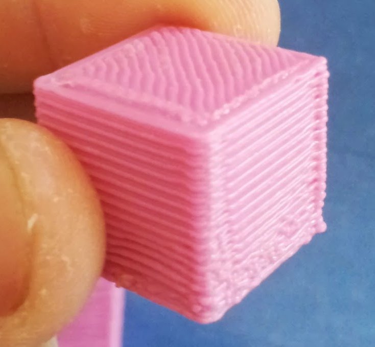
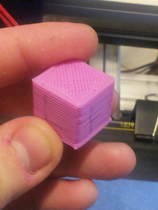
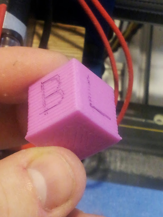
Here is a picture of my last configuration cube taken from the side.
It also looks like I'm smooshing the beginning of the print against the bed too much. I figure that is just a setting in slicer to move the initial layer up a touch. I think I saw something about that and maybe also adjust the setting in slicer that controls how much plastic is extruded to a slightly higher value.
Anyone have some other suggestions about where I need to tweak or what I could do to improve that Z wobble.
Comment from: kbob on Sunday, June 9th 2013 - 7:13 PM
I'd like to see a nicely carved hardwood carriage. That would be the bee's knees.
Sunday, June 9th 2013 - 4:13 PM
Thanks Enraged, I just did the mark and measure of 30mm of plastic mentioned in that link you posted while using Bart's measurements and it seems good. This makes me think I have some other setting that is potentially a problem. I just don't know what. Maybe I should start looking around Slic3r.
Yeah, that mount gets the job done for now. It's real solid and I like a bit of wood in the mix.
EDIT: Hmm... it probably helps to give it the right filament size... 1.75, not 3mm. I should have looked at the slic3r settings sooner.
Yesterday we were able to play and rework. Oddly, after I mounted the extruder firmly instead of using the zip ties that allowed it wiggle room, my print walls actually looked like every 4th layer was off or something. Previous prints looked like the layers were all aligned. It's also fun to note that my daughter knows to type in M119 when I say "check the endstops".
I also was just using the default setting for EXT0_STEPS_PER_MM of 413 and it was clearly extruding a bit much. I changed that to 95.9 per bdring's measurement. This seems to be insufficient as the prints after that were stringy. I guess i need something in between.
With EXT0_STEPS_PER_MM 413 (Repetier Default)
With EXT0_STEPS_PER_MM 95.9
My more firm mounting solution for the extruder, for now. I'll come up with something better later... maybe.
My daughter is back home (along with the rest of the family) so we took some time to put the first bit of plastic through the EZstruder and j-Head. I think these pictures speak for themselves.
You might say I'm a bit more motivated to figure out what it Repetier-firmware or host is blocking the use of the Z-axis.
When I load the Panucatt X3 Test code, it moves everything around, heats things up and generally acts much better than it did before I had the microstep jumpers in place. However, when I load the Repetier firmware on it, the Z does nothing. It does lock the motors, but it doesn't rotate. Any ideas why?
Here is a video of my Hadron doing its best to print a cube via Repetier Host and Slic3r.
EDIT: Also, I found that the ruler I was using that I thought was metric, wasn't. My 100mm run is indeed almost exactly 100mm when using a metric ruler and not an imperial one. <-- crazy yank, can't measure right in a base 10 system
I wired up the thermistors, j-head and helios this evening. Things are getting hot and holding temperature really well even with the ceiling fan. It's fun to watch the blinking red lights on the Azteeg X3 and Helios Hotbed go at it. It feels like life is coming to the machine.
I also completed the power supply mod. I used some spade terminals to run the wires into the Azteeg. Here you can see the two twisted black and the two twisted yellow in a sheath running off to the power supply. I also twisted two black and yellow for the heated bed to be sure I could handle the load without any problems since I didn't have a wire gage I was completely comfortable with and I kinda like twisted wire. (I've probably spent to much time with Cat5.) Also, the light fol the hotend and hotbed are on! So you can't really see much in this image except that it's there, but I really like the look of the heat cartridge. The red on it matches the red on the EZStruder nicely. Also, I found I could, at least temporarily run the wire for the thermistor through the adapter plate's opposing side to hold it firm and steady. Also, if you have sharp enough eyes, you'll see that the extruder is simply zip-tied to the carriage at the moment.
Proof, cause software don't lie...
I'm avoiding putting any plastic through it yet because my daughter isn't around and I'd like to share that with her. I have plenty to do that isn't educational or exciting for a 6yr. old. I'll explain to her what I did, but the actual doing would simply cause her to lose attention as I think, try, think, try, think and think some more.
Occasionally, my tendency to take things apart and collect parts comes in handy. I found four great springs that match each other exactly in my collection of bits. I did find that I don't have the thermistor I was planning to put in place, but then I don't have any J-B Weld to get it properly placed either so that'll wait. didn't realize when I ordered it that the Helios heated bed has pads to solder the thermistor to and bring it out to the edge of the board. That's a neat feature. I also need to get some Kapton tape to secure the edges of the insulator strips. It sure does look nice though.
My junk pile spring find
Any suggestions on mounting the glass on top of the heated bed?
I have imagined a few different ways, but would appreciate the benefit of others experience. I assume any mounting solution should not rise above the edge of the bed?
My daughter dutifully recording a shopping list.
Oh, and my pulleys are 20-teeth pulleys so those calculations should be pretty good.
Gadroc wrote:The Ord Bot is not as standard as you're thinking, it's more of mechanical platform than it is a full printer.
Granted, I'm comparing it to the choices some friends of mine are making in building a RepRap Prusa Mendel right now. They have a lot more info they have to slog through, much of it in conflict with each other. When it came to the mechanical platform, where I am most weak in knowledge, it was easy. In the electronics, I have some foundation to build the knowledge on and am more comfortable there.
Comment from: Gadroc on Wednesday, May 29th 2013 - 2:56 PM
flickerfly wrote:Is there a place you'd recommend where the calculations are all in once place and up-to-date?
As you pointed out, there are tons of sources of varying ages and correctness. There is a ton of time in doing that and little of that can I share with my 6yr old. Going with the Ord Bot has the fortunate advantage of skipping some of this since the platform is pretty consistent. (Thanks bdring!)
I use the Prusa's calculators as well. The Ord Bot is not as standard as you're thinking, it's more of mechanical platform than it is a full printer. Some other builds specify a lot more down to which electronics, hot-end, belt type, etc... Those have more "out of the box" numbers or even standard firmware (see Mendel90, Tantillus, RepRapPro Mendel, etc..) That being said I'm very happy with my Ord Bot setup, but you'll find much much less information online about calibrating and configuring it than you will a more "full build" machine like some of the others. That is not to say people don't constantly tweak / change them but it seems there is usually a bigger base of people using the stock build than we see on the Ord Bot.
Wednesday, May 29th 2013 - 2:33 PM
Gadroc wrote:it's best practice now a days to stick with the mathematically calculated values.
Is there a place you'd recommend where the calculations are all in once place and up-to-date?
As you pointed out, there are tons of sources of varying ages and correctness. There is a ton of time in doing that and little of that can I share with my 6yr old. Going with the Ord Bot has the fortunate advantage of skipping some of this since the platform is pretty consistent. (Thanks bdring!)
Comment from: Gadroc on Wednesday, May 29th 2013 - 2:15 PM
As far as I can tell (a lot of the calibration Wiki's in the reprap world are outdated) it's best practice now a days to stick with the mathematically calculated values. They should be "close enough" and if not it's probably a mechanical error. This is especially true for an Ord Bot with manufactured pulleys instead of printed ones. If you are calibrating to a test object your calibration might only be accurate on objects that exact size, then when you print a larger item the errors you compensated for will then become bigger errors. In this case the math is way to far off of actual to start "fine tuning".
Comment from: Winder on Wednesday, May 29th 2013 - 2:02 PM
I tried calculating what the settings should be and came up with a number close to yours. Once getting to that point I started printing out this nickel test object: http://www.thingiverse.com/thing:11261
After printing I would see how well it fit and adjust my settings slightly to bring it closer in, I printed 3-4 of these total to get a nice fit. In an ideal world I would have liked to calculate the settings to get them bang on, but this was pretty easy and was effective enough for me.
Wednesday, May 29th 2013 - 1:19 PM
Thank you Gadroc. I wouldn't have thought to actually count the teeth. The ATI Shipping List also says it has 20 teeth, but if you had 18 I better check that when I get home. I can certainly see how that would make a difference.
I'm fairly confident given another look at my stepper's data sheet that 1.8 deg/step is accurate for that stepper. I'll look at the X3 board again and make sure I didn't confuse the 1/16 jumper settings with the 1/32. That's all done with jumpers on the board right? There isn't any settings in the firmware to make in addition?
Comment from: Gadroc on Wednesday, May 29th 2013 - 12:18 PM
For your X/Y it looks like you have two problems. One it looks like either you have a 0.9degree steppers or you have set micro-stepping to 1/32. Second your pulley tooth count may be wrong. Looking at ATI's website looks like they are reselling reprapdiscount products now, and when I my kit from reprapdiscount I got 18 tooth pulleys not 20. I would actually count the teeth on your pulley.
2560 is accurate given 1.8degree steppers. Double check that as well.
I decided that to make this calculation I needed to enter the following info into the "Steps per millimeter - belt driven systems" calculator. Note: Repetier now has this calculator built into their software in the Tools menu. It comes out with similar, but perhaps more precise numbers. (78.8177 on the belts.)
Motor Step Angle: 1.8degree Driver microstepping: 1/16 Belt Presets: MXL Pulley Tooth Count: 20
Results: 78.82 steps/mm (X & Y Axis)
I went into Repetier host, hit Alt + E to open up the firmware settings and put that in for the X and Y. Suddenly, things started to move as expected over distances that are much closer to accurate. The distances aren't bang on, in fact they are actually off by a lot, but that's an improvement. I measured the X-axis with a 100mm move and it went 39mm. Clearly some work needs to be done.
Over the two short period that I had this up and running, the drivers became extremely hot; the Y driver was almost to the point of burning to the touch the first time and the next it was was the Z driver (which still doesn't move). I'm letting them cool down right now. My first instinct after cutting the power was to turn the pots down a little bit. The drivers are sometimes making lots of whiny noise in certain positions, but they were doing that before.
While I was playing with Prusa's calculators, I also tried out the "Optimal layer height for your Z axis" calculator. I found out the following using the M8 lead screw preset giving me 1.25mm/revolution. I'm not sure what this chart does for me at this point, but I'm plopping it here for later reference.
Oh, and the "Steps per millimeter - leadscrew driven systems" calculator from the same place is relevant to the Z so here's the result of that calculation using nothing not already mentioned in this post.
Results: 2560 steps/mm (Z Axis)
Dragging this over from the SeeMeCNC EZStruder post so I have things gathered:
bdring wrote:I measured the steps per millimeter of the SeeMeCNC EzStuder at about 95.9 stes/mm
DEFAULT_AXIS_STEPS_PER_UNIT in Marlin EXT0_STEPS_PER_MM in Repetier
NOTE: These aren't well tested and tuned values, just some calculations that will hopefully get me in the ballpark.
Finally getting a chance to come back to this. My daughter and I played with it some and make things move a bit. I'm not sure where to find the right information on calibration and I'm not certain my power supply of choice is actually powerful enough. I feel a sharp rise in the learning curve coming on.
So, I (think) I have all the stuff. I've rigged up the X3 with the motors and the X and Y axis move around some. The Z-Axis doesn't at all though it holds its position and won't manually move easily once given a command. I have the repetier firmware and host 0.85b that I'm playing with. When I manually tell both the X and Y axis to move 1mm it seems a smaller move or awfully close to the same as the 0.1mm move. When I tell them to move 10mm, they don't move at all.
Anyway, I'm going to play with it some more tonight and try to get the endstops hooked up and verified as functional.
EDIT: Okay, I found that the travel of both the X and Y in repetier is a total of 12 (is that mm?) rather than the 200 I was expecting. I guess that probably means I have some firmware config issues.
Comment from: bwevans on Tuesday, May 14th 2013 - 6:15 PM
Thanks for the info, best of luck on the rest of the build!
Tuesday, May 14th 2013 - 5:56 PM
bwevans wrote:How long did it take between ordering and receiving the kit from ATI?
It was real fast, as fast as anything I ordered. I ordered on May 4th and it arrived May 8th. It originated in Palatine, IL and was shipped UPS. It came in great shape. I've since ordered another item from them on Sunday. USPS says it'll be here Thursday. Smaller package so USPS makes more sense. Also, they are on the list of companies that pay royalties back to Bart for the design so that's a plus also. The only complaint I had turned out to be my own fault. It does not come with holes for the cables drilled in the makerslide, but I'm not sure how I want to do that yet anyway so I appreciate the flexibility.
Comment from: bwevans on Tuesday, May 14th 2013 - 5:45 PM
How long did it take between ordering and receiving the kit from ATI?
Saturday, May 11th 2013 - 9:18 PM
My daughter is under the weather so the build didn't progress, but we did buy what I think are the last few things we need. Since the J-heads can be purchased in parts from hotends.com we did that. We also opted for a heater cartridge. In a moment of mental drop-out I ended up with two steppers, That may come in handy anyway.
Today's purchase
Role Desc Qty Supplier Price S&H, Taxes Total HotEnd Parts for a J-Head 1 Hotends.com 53.33 11.41 64.74 Ext/hotend bits NEMA 17 & Heater Cartridge 1 Ebay: rp_one_labs 19.8 3.95 23.75 ABS 1.75 ABS Pink Plastic Spool 1 Octave 31 5.5 36.5 Extruder Stepper NEMA 17 Stepper Motor 1 ATI 9.99 6.89 16.88
Thanks Bart. I may have over-tightened then. I have it resting now. Otherwise, I'll just need to pickup a few spares I guess. I could see having more fun with this maker slide stuff some more so couldn't hurt to start building an inventory.
In other news, Hotends.com doesn't seem to have make any J-Head's available today, unless I missed the small window of availability.
Comment from: bdring on Friday, May 10th 2013 - 7:25 PM
No saying this is the problem, but....
The wheels should only be snug. If you over tighten you can put a flat on them. Sometimes the wheel will recover if you let it sit.
Friday, May 10th 2013 - 6:03 PM
Thanks, I did all that. It seems to be the wheels. I tried running them on another rail, but shorter and didn't notice it. I also ran each wheel separately against the rails and didn't notice it. One might be a little flatter in the point of the V maybe. I think I'll try swapping that with another one and try that.
Comment from: TLHarrell on Friday, May 10th 2013 - 3:56 PM
On the Y-axis, pull off the belt. If the problem goes away, it was the belt or motor. If the problem remains and is cyclical, it's the wheels. If the problem remains and is in only one spot, it's the rail.
Friday, May 10th 2013 - 4:50 AM
While it isn't a literal dumpster dive, but rather a nicely sorted hackerspace full of stuff, I found what I believe is an ideal power supply for the price of $0 in the MakeLehighValley cast-off pile. We have a big box of ATX power supplies. I was just walking by as a guy was emptying the box looking for a particular one and I saw this! It has 16A at 12V so I believe that is right where I've heard it needs to be. I'll have to look at the Azteeg X3 to see if it would help to bring the 5V up also to run the controller.
While properly plugged in and the green power line jumped to ground, it comes up and hums nicely.
I've done power supply mods before and found them to be pretty easy. This thing has AC and a switch on the back and DC out the front. I'm thinking I may put a switch for power up front where the DC stuff is coming out now and look at running the 12V discreetly out the top and directly into the makerslide.
I also managed to basically get the platform standing. I feel confident that I can go through it with my daughter at this point without stopping and thinking a bunch and losing her attention as a result.
I was having some trouble with the bed carriage. It seems to move unevenly on the rail like there is a bump somewhere that I need to figure out. Any tips on where to look for this problem? I examined the V-wheels and the V-rails and they both seemed smooth to the eye. I'll give it all a more thorough look as I'm taking it apart I guess.
Update on the missing ATI parts: Apparently they aren't missing. I was working from the wrong list. The ATI shipping list doesn't include them and includes a few extra of the BHCSM508S screws. I finger tightened some of those in place quick and they seem to work so is my error in assumption.
TLHarrell wrote:Either your wife is really, really young looking, or you have a helper for putting together your project that will print a ton of Barbie stuff. Hope you've stocked up on pink filament.
That's a good looking kit. I'm a tad bit jealous.
Yeah, it looks beautiful. I should wax and buff it. My wife is also well cherished, but my 6yr old and I are building this together. She and I saved up for it and she's been talking about it for quite awhile, educating grandparents and the works. (I've observerd that people listen to her geek out more than me.) Doll house furniture is one of the many, many things on her list. I hope someone build a 3D design product appropriate for such young minds. Maybe we can do some playdough creations and use 123D Catch to make them digital. I haven't quite figured out how to help her engage the design part of 3D printing yet, but we're going to explore it.
Just received my email from Panucatt that my shipping order was made. I guess those will enter the UPS system some time today.
I pre-ordered the SeeMeCNC EZStruder Extruder Kit. I'm probably overly impressed with the RostockMax so wanted to get something from them and that kit looks to be such a good intro price and I'm an easy sell when flexibility is high on the feature list. The one downside is that it won't ship until May 20th, but that'll be encouragment for me to make sure the mechanical platform is in great shape and wired up pretty.
Which reminds me, I realized last night that there are no holes drilled in ATI's extrusions for running the wires. I had no expectation one way or the other, but it seems worth recording that this is the case for someone looking for that information. I'll be looking to use the drill press at the hackerspace to resolve that since appearance and kid-proofing are priorities for me, but not until I have a good idea of where to drill.
Any tips on how to make the wiring hole location decisions? Mistakes to avoid?
Update: SeeMeCNC is shipping today so I must have just slipped in my order in time. They sent me an email saying it was on the way out the door.
Comment from: TLHarrell on Thursday, May 9th 2013 - 5:07 PM
Either your wife is really, really young looking, or you have a helper for putting together your project that will print a ton of Barbie stuff. Hope you've stocked up on pink filament.
That's a good looking kit. I'm a tad bit jealous.
Thursday, May 9th 2013 - 4:08 AM
My wife's first response when she saw it all out of the box was "Ooo pretty. I like the blue!" (score!)
The ATI kit came with the V-Wheels and the Idlers pre-assembled. I sorted all the items. I think I have a problem where the motor brackets were in a bag labeled #17 which is actually the M5 x 6mm Button Head Cap Screws and I didn't get those screws in the box. I can totally see that getting past the double check. Packing was good and all the parts looks to be nice, straight and a consistent blue color where appropriate. The extrusions are all properly sized. Update: this was my error I was using the wrong list - The ATI shipping list.
I guess I'm going to put tons of images on a Google+ album. Here are some highlights from tonight.
I do know a couple machinists at church. Maybe I can see if one of them would be willing to help me out with modifying the QU-BD extruder. It doesn't seem like it'd take someone who knows what they're doing very long. It looks like everything I'd need to ask of them is in this post: viewtopic.php?f=27&t=1977
Oh... My mechanical platform is here. ATI was quick about it. I'm not going to open it until I'm done working. It is enough of a distraction already.
The short answer is no. The long one involves lots of paperwork and boring details about liability, training and not letting people wrap their arms around the lathe. We have made progress though.
Comment from: JeremyBP on Monday, May 6th 2013 - 2:21 PM
I don't think he meant to drill out the nozzle, but rather the stainless thermal barrier.
Did you guys ever get that lathe set up? That would be the ideal way to do it.
Monday, May 6th 2013 - 2:43 AM
bloomingtonmike wrote:QUBD Nema17 and 12V heater cart equipped MBE extruder $70 shipped, PTFE teflon tube for nozzle ($2 if you want some), Barts MK7 gear and his tensioner system $25, = sweet 1.75mm low profile solution. You will drill the barrel for the teflon tube, get rid of the QUBD tension pin and their uhmw block, install the Bart mods and it is super awesome IMO.
Okay, I think I've read up enough to catch what you're saying here. You're suggesting that purchasing the QUBD with a heater cartridge and applying the modifications to make it reliable is the way to go, right. My big issue is the drilling of the nozzle. I don't have any experience with machining parts. I've done some home remodeling, a touch of wood working and took a shop class with some welding in it in high school. I also don't have easy access to a drill press with a vise. How likely am I to irrevocably mess my nozzle up?
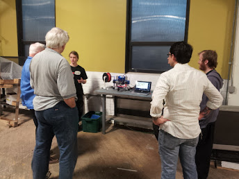
Thanks Jeremy! Feel free to share your advice any time. I've used that picture I attached for advertising the hackerspace because I can point out the diversity of the hackerspace in terms of age and occupation. We have retired college prof learning from a high schooler while an economic development professional, a blender artist and an electronics wizard listen in. Then there is me, a sysadmin, behind the camera thinking about how cool Jeremy had it to grow up around a machine shop.
Something I haven't mentioned yet, but will probably show up in the pictures later. My 6yr old daughter and I have been saving up for this printer for awhile now. She's really excited. She sat in my lap this afternoon as I shared with her what I'd ordered and how things were going to go together this afternoon. What a great Daddy/Daughter activity, assembling a 3D printer together! Maybe in a couple years my son and I can assemble a laser cutter. He's only 2yr old now so not quite catching the vision although he does like the "train tracks" and "wheels" of the ORD Bot so that's a plus.
That brings up another thing I need to figure out. I need to make sure that when this thing is printing, they can watch but not touch the hot parts. I can probably train the older two, but there is also my 9mo old daughter. I may build an acrylic fence for it or something similar as I do want them to see it in action. I'm thinking a 3D printer in the house may just be like my Dad having Internet access in our house and bringing home Linux from the faster connection at work from when I was very young, giving me skills to be at the forefront of cultural change and having skills that are valuable within that context.
Comment from: JeremyBP on Monday, May 6th 2013 - 1:05 AM
'Sup.
I'm glad you're finally starting a printer. I'll be following along.
Sunday, May 5th 2013 - 10:58 PM
Thanks bloomingtonmike.
I've read over what you posted three times and I understand most of the terms you are using, but I'm not sure what you are proposing or if you are proposing two options. What is a heat cart? Would you mind clarifying the rest a bit for me? (Newb in da house)
Strike that, I figured out what you're talking about and made another comment further down with a question.
Comment from: bloomingtonmike on Sunday, May 5th 2013 - 4:44 AM
QUBD Nema17 and 12V heater cart equipped MBE extruder $70 shipped, PTFE teflon tube for nozzle ($2 if you want some), Barts MK7 gear and his tensioner system $25, = sweet 1.75mm low profile solution. You will drill the barrel for the teflon tube, get rid of the QUBD tension pin and their uhmw block, install the Bart mods and it is super awesome IMO.
Saturday, May 4th 2013 - 9:53 PM
First ORD Bot Exposure Just for community interest... I first saw an ORD Bot when a guy came by Make Lehigh Valley, a hackerspace in which I'm a member. His name was Jeremy and he was checking out engineering schools near hackerspaces and planned to make the hackerspaces an important part of his decision. Brilliant! I assume he didn't end up near us as I haven't seen him since. (Where are you Jeremy?) Anyway, I was impressed and have had it in the back of my mind for awhile. I deviated for awhile looking fondly at the SeeMeCNC RostockMax, but I have returned and now invested in parts.
Objectives Quality and appearance are probably the top two priorities I have for this printer. Ease of assembly and flexibility for future improvements are secondary priorities (as I'd like to get printing before very long and I'd like to be able to improve it). Then price is the third priority.
Parts I've updated this since writing some of the other things here so there are some minor inconsistencies. The list is the most up-to-date. I've made links to where you can purchase each item on the item name and where applicable the reprap.org wiki page as that seems to be the best location for technical data on each part. Also, I don't recommend getting extra bits from Panucatt. They may not make it into the box.
I chose Panucatt for their reputation on the forums, my personal interaction with Roy (the owner) and the nice finished look of the board. I chose ATI because of their reputation on the forums and because I wanted the experience of assembling the mechanical platform, but not confident in machining it.
Extruder is still TBD - I'll probably try to scavange a stepper, springs, bolts, etc. and arrange prints for much of this. I'm considering the purchase the J-Head hotend I might try to put Steve's Bowden onto the bot and machine a custom carriage for it, hiding the stepper and gears back with the controller. I'd also like to mount the tip of the hotend as high as possible to give me lots of height for my prints. I'm very open to thoughts on this so feel free to add your ideas and opinions in the forum post I started on this.
In the end, indecision will probably force me to duct tape a sharpie to the extruder carriage for initial tests of the controller board.


 add comment in the forum
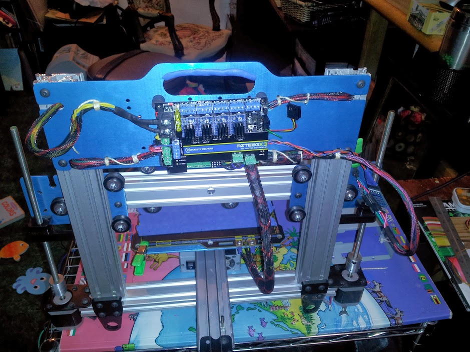


 From Thing:39994
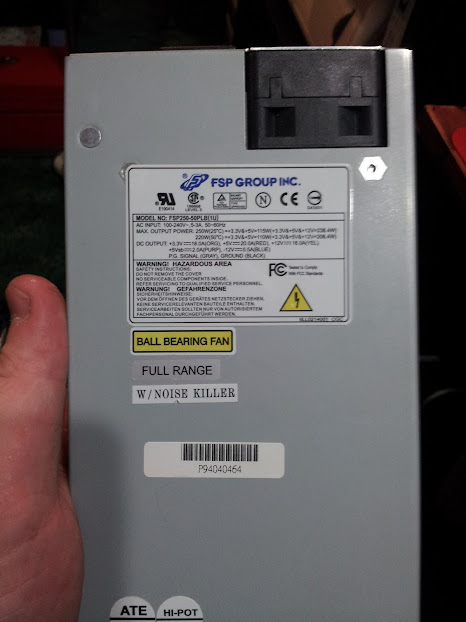